QuickCAD Truss Winding
 Cadfil Help contents
  Cadfil.com Home
Overview and Terminology
This Cadfil feature provides a quick parametric input to create a winding program for a composite truss structure. This truss structure will have two separate types of program helical and axial that will need to be combined. Additionally hoop winding using the Multihoop option may be employed to add to the end zones.
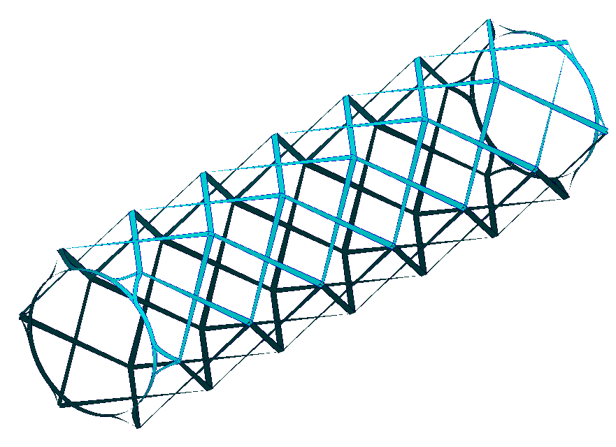
Axial Programs
The first type of program, or axial program winds a 0 degree layer parallel with the mandrel rotation axis. At the end of the mandrel there will be some rotation before another 0 degree pass occurs in the opposite direction. In practice there will need to be some physical structure on the mandrel that will force the fibre to stay on this path, otherwise it will slip as the mandrel rotates. The axial layer will look similar to the example below, showing an axial layer for a 6 sided truss. These have parameters with the TRS-TYPE set the "Axial".
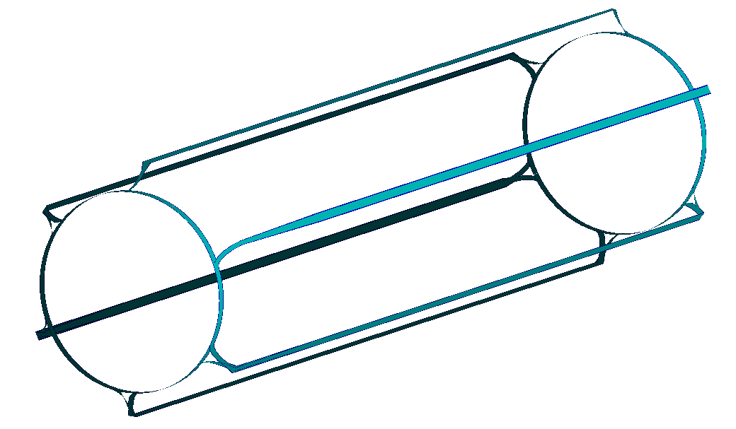
Helical Programs
The second type of program, or helical program will wind at an angle so that it connects the different axial fibres together. The helical pattern in the positive direction will intersect with the helical pattern in the negative direction at the same point as it crosses an axial fibre. For one complete layer, the number of circuits must be equal to the number of sides that the truss has, so that each point at the end of the mandrel has both a positive and negative direction fibre that leads to it. The helical layer will look similar to the example below, showing an axial layer for a 6 sided truss.These have parameters with the TRS-TYPE set the "Helical".
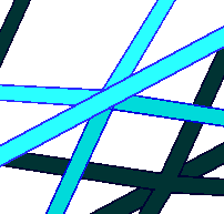
Nodes
The nodes are the places where the axial and helical layers cross. Each node will look like a 6 way junction from the 3 different fibre directions; axial, helical (+ direction) and helical (- direction). The picture below shows an example of 1 node. The nodes are equally spaced along the axial stringers. The node spacing determines the helical angle for helical layers. Specifying the number of nodes was considered to be a more robust method than trying to specify the helical angle which in reality will not be a round number, whilst the number of nodes is fundamental to the mandrel design.
Stringers
A Stringer is another name for axial rib. The stringers in the axial layer will make up the sides of the truss. In the example above, there are 6 stringers, creating a 6 sided (hexagonal) truss.
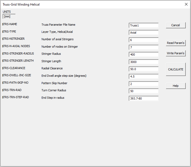
The Truss Winding Dialog
The picture below shows the truss winding dialog. This shows a set of parameters which can be input to create a axial or helical layer.
Truss name
This is the name of the job and is used for the various output file types that can be created.
Truss Type
There are 2 options here, this can be either 'Axial' or 'Helical' depending on the type of layer that is being created.
Number of stringers
The number of stringers as discussed above. The stringers are assumed to be equally spaced
Number of nodes
The number of nodes along one stringer. The actual total number of nodes on the entire mandrel will be the Number of Nodes multiplied by the number of stringers. The nodes are equally spaced along the stringer. Remember as there is a node at each end there will be N-1 divisions of the length.
Stringer radius
The axial distance from the central (winding) axis to one of the stringers. This value will be the same for any stringer, as they should all be the same distance from the axis.
Stringer length
The length of one stringer in the carriage direction. It is important that these values are accurate otherwise the routines to ensure that fibre transitions correctly from mandrel groove to mandrel grove at the ends my be compromised.
Radial Clearance
The clearance value for the envelope when calculating machine positions. This is the radial clearance value from the Stringer radius, not from the axis so the payout will be normally at a distance stringer radius + clearance from the winding axis.
End dwell angle step size
In the turning path at each end there is an amount of pure rotation (dwell). This will be divided into a number of positions such that the rotation from one position to the next does not exceed this step size value which is specified in degrees. So if the total dwell was 60 degrees and the step is 18 degrees then three divisions would be 20 degrees which is more than 18 degrees so 4 divisions of 15 degrees would be used 15 being less than 18.
Pattern skip number
After completing a stringer, the pattern will 'skip' a set number of sides by dwelling before winding the next stringer. The number of sides skipped is set by the pattern skip number which is an important part of the end transition motion. However in most cases the rotation will not create a pattern which fills all the slots so on some circuit at the initial end Cadfil will automatically increase the skip by one for that specific turn such that all slots are filled. In the Cadfil text window a summary of the order the slots are filled is given.
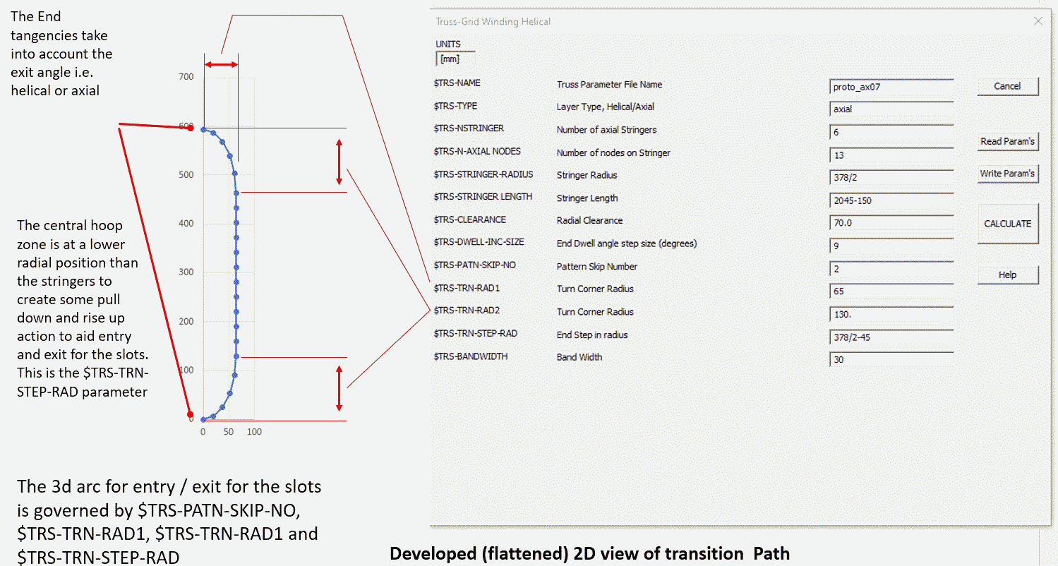
$TRS-TRN-RAD1 Turn corner radius 1
When a fibre path exits a groove (channel) end for an helical or axial path, the path makes a transition to the hoop (circumferential) direction. The path then winds and amount at pure hoop and then makes a transition to enter a new groove for the return path. Because of the need to ensure that the fibre is firmly lock down into the exit groove the transition paths need careful design, otherwise the rotation of the mandrel can cause the fibre to pull out of the groove. One it is firmly locked down and and the mandrel has rotated a certain amount the fibre will be fully secured. The translon path exit in initially tangential to the groove. The transition path is a quarter of a full ellipse with the half axis lengths of $TRS-TRN-RAD1 and $TRS-TRN-RAD2 with the former in the axial direction and the latter in the circumferential direction. This elliptical path is notionally along the surface of a cylinder of radius Stringer radius ($TRS-STRINGER-RADIUS). However, because we want the payout eye to move in radially a small amount to help the catch in the exit slot we have a further parameter $TRS-TRN-STEP-RAD which is a radius a little smaller than the stringer radius. So the elliptical path linearly moves inwards between the $TRS-STRINGER-RADIUS and $TRS-TRN-STEP-RAD. This is perhaps easier to understand in the diagram shown below.
Turn corner radius 2
See the topic $TRS-TRN-RAD1 above
End step in radius
See the topic $TRS-TRN-RAD1 above
Band width
This is the width of a single band. This value will not affect the position of the fibre path in any way, and is not used in calculation as it would be if the mandrel were a pipe or a pressure vessel. The bandwidth will only change how the fibre band is displayed within the software by changing the width of the band in the graphics.
Return to top of page