Sphere Parametric
 Cadfil Help contents
  Cadfil.com Home
Overview
The sphere parametric automatically creates multiple layer winding programs to make a multi-angle layup on spherical components. The programs can give near uniform thickness distribution particularly if the filament bands are thin and a large number of layers are used. Because multiple wind angles are used the resulting composite is effectively in-plane quasi-isotropic and this gives maximum efficiency for a spherical pressure vessel. Ultra-high performance pressure vessels have been produced and tested using this method.
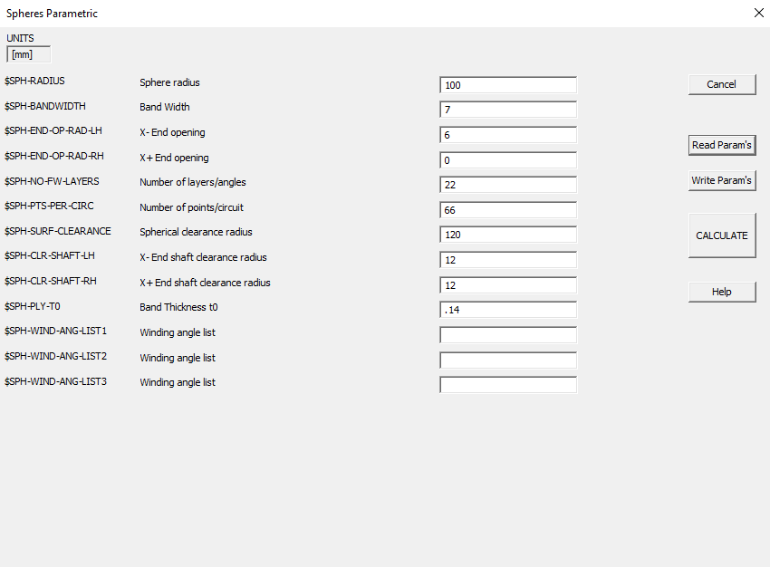
QuickCAD Sphere Winding Parameter
The user defines the sphere geometry (radius and end opening radius) and material parameters such as the band width and thickness and the number of individual winding angles that are required. The program then creates all the necessary winding path information and transition paths that wind from the end point of one path to the start point of the next. The parametric program is invoked from the QuickCAD options of the Cadfil main menu.
The program generates a series of .PAY files for example if the parametric data was in the file SP.PAR the software would generate SP01.PAY, SP02.PAY, SP03.PAY....... A maximum of 99 payout files can be created. A special control (list) file SP.CTL would also be created. When the data is post-processed the .ctl file identifies all the individual .PAY files such that they can be automatically processed in sequence to create a single NC winding program.
A combined winding ( 'job-name'.CTL ) file is automatically created that includes all the .pay files. This can be post-processed to make the full winding program or used in the View Multiple payout files option to see the complete winding. Thickness files (.TH2) for each layer are also automatically created as well as a thickness list file 'jobname'_th2_lst.txt. This can be used as an input in the option to create finite element analysis output.
Program Parameters
Sphere radius
$SPH-RADIUS is the radius of the spherical mandrel. For Cadfil sphere this should be a constant radius.
Band Width
$SPH-BANDWIDTH is the true band width of the fibre bundle/tape.
X- End opening
$SPH-END-OP-RAD-LH is the radius of the end opening at the X- (left) end, where no winding takes place. Normally the mandrel would have a boss or fill tube.
X+ End opening
$SPH-END-OP-RAD-RH is the radius of the end opening at the X+ (right) end, where no winding takes place. This can be set to 0 if there is only an opening at one end.
Number of layers/angles
$SPH-NO-FW-LAYERSis the number of different angles which are required. For an even thickness distribution, this can be calculated by dividing a quarter of the spherical circumference by the bandwidth.
Number of points/circuit
$SPH-PTS-PER-CIRC. Each winding program has a number of data points on it and this is the number of points per circuit. A value of 20 works well in most applications. This is a compromise between accuracy and the amount of data created.
Spherical clearance radius
$SPH-SURF-CLEARANCE is the clearance value for the machine. This should include the mandrel radius, and therefore the value should always be greater than the Sphere radius defined above.
X- End shaft clearance radius
$SPH-CLR-SHAFT-LH is the required machine clearance from the X- (left shaft)
X+ End shaft clearance radius
$SPH-CLR-SHAFT-RH is the required machine clearance from the X+ (right shaft)
Band Thickness t0
$SPH-PLY-T0 is the thickness of an individual fibre band used for thickness calculations.
Winding angle list
$SPH-WIND-ANG-LIST1 is a list of required winding angles if this is required. This line is normally left empty as the winding angles are automatically calculated from the number of layers/band sets. If used these values and wind angles (in degrees) commas or spaces. e.g. 10.0,15.0,20.0,25.0
Winding angle list
$SPH-WIND-ANG-LIST2 is a list of required winding angles if this is required. these will take the appearance of numbers separated by commas or spaces. This second line is available in case there is not enough space on the first line. The three lines are combined when the calculations occur.
Winding angle list
$SPH-WIND-ANG-LIST3 is a list of required winding angles if this is required. these will take the appearance of numbers separated by commas or spaces. This third line is available in case there is not enough space on the second line. The three lines are combined when the calculations occur.
More information
The Sphere radius and polar end opening define the winding geometry. The polar end opening is at both ends and the inner edge of the fibre band for the lowest wind angle should just touch the opening diameter. The highest wind angle is 90 degrees and this is a single band around the equator. A number of winding angles (layers) are created equal to the number of bands sets with constant changes in wind angle between the highest and lowest angles layers described above. Each program is a separate standard axisymmetric program with the number of cycles required to complete the layer automatically calculated. The wind angles, numbers of bands in the layer and the name of the particular PAY file are tabulated on the screen when the Sphere program is invoked. If the basic thickness of a filament band was say 0.18mm and a composite 4mm thick is required then 4/(2*0.18)=11.1 layers are required and the number of band sets would be specified as 11. In practice the actual thickness of the part will vary a little. We have found that the composite is often a little thinner at the poles and the lower angle winding programs can be repeated (by changing the number of cycles in the NC data) to thickness the composite at the ends.
The spherical clearance radius and end shaft clearance radius define a control surface on which the payout points will lie. This consists of a sphere intersected with a cylinder, the cylinder being bigger than the mandrel shafts(s) and the sphere being bigger than the mandrel (plus the thickness of the winding). Thus the values supplied must be bigger than the shaft and mandrel radii.
When post processing the payout data from the sphere program the user should note that the band pattern has automatically been calculated in producing the payout file data.