Elbow parametric data entry
 Cadfil Help contents
  Cadfil.com Home
R, Rc, A, L, Yoff define the mandrel geometry are shown in the figure below. The mandrel axes are also shown. The sign of Yoff is important as this is measured in the mandrel Y direction from the mandrel origin to the wind axis.
The point per rotation (N) defines the number of data points per rotation on the fibre track around the mandrel a small value (e.g. less then 8) could lead to inaccuracy in the winding. A large value leads to an increase in the size of data files and the final NC data. For most purposes a value of 12 is a good compromise.
The band width (Bw) is the actual width of the fibre tape or band that will govern the separation of the fibre paths on the mandrel surface.
For clearance method 1, the clearance is the Free fibre length (Fl) which is the distance between the fibre contact point on the mandrel, and the control point at the end of the payout device on the winding machine. If this distance is very short, the risks of contact with the machine and the mandrel are much greater. Because of the complexity of winding head geometries (particularly on 6 axis machines) it is not possible to guarantee that there will be clearance between the mandrel and machine at all orientations and positions. When winding an NC program for the first time it should always be run slowly such that the user can check clearance and stop the machine quickly if necessary. It may be necessary to re-generate the program with a greater free fibre length or to use a different postprocessing control strategy. You can of course use the payout path viewing options to check machine clearance also.
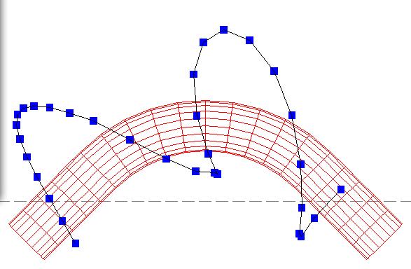
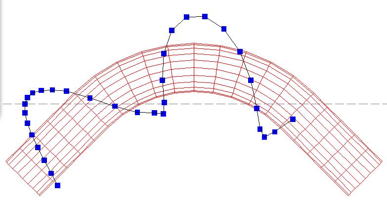
The picture above left shows part of a payout path from the Payout path viewing options. Each blue mark represents the position of the feed-eye, it is easier to imaging the mandrel as being stationary and the feed rotation around the mandrel. Near the centre of this path a problem is evident as the paths circulates around the mandrel but does not circulate around the winding axis (the dashed line). This cannot be wound and if post-processes the mandrel will rock forwards and backwards. The solutions are to adjust the wind axis position or to increase the clearance (free fibre length). The same winding with the problem fixed can be seen in the picture above right.
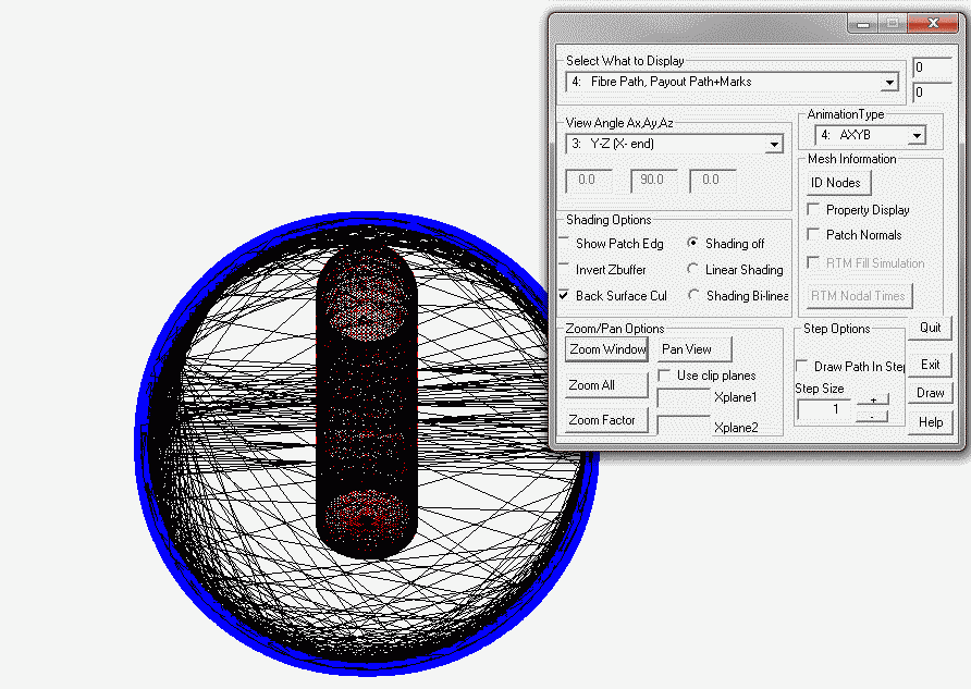
If clearance method 2 is selected, the clearance value is the Control Cylinder Radius. The radius dimension entered is required to be greater than the maximum radial point of the mandrel away from the winding axis to be used. This enables the winding of an elbow component on machines without a cross-feed axis, or only a manual cross-feed axis. For a two axis mode the over-travel past the ends can become large so the range of practical elbow geometries that can be wound is significantly reduced. The image below show a payout points (blue dots) on the cylinder when viewed along the mandrel axis. This view is useful in checking that the radius chosen makes sense, i.e. not too large or small.
The friction coefficient Mu is used to provide a none slip fibre turnaround at the mandrel ends. The fibre is progressively turned around at the outer end of the parallel length. The higher the value the shorter then length of the turn around will be. Values in the range 0.01 to 0.25 are usually used but this will vary with materials being used. It may not be possible to turn the fibre around if the friction coefficient is too small or the parallel length of the elbow is too short. The program will issue an error if this condition exists.
Wind angle (degrees) Alpha this is the helix angle of the fibres on the mandrel surface with respect the winding axis. This angle is maintained at all locations except the turning zone at the mandrel ends. Because of geometric constraints of fibre bridging across the inside of the elbow or fibre slippage it is not possible to use low angles. The program does not permit angles less than 45 degrees though if the bend radius is tight the minimum wind angle that can be used in practice may be higher than this.