Aluminium Liner winding ‐ Parametric method
 Cadfil Help contents
  Cadfil.com Home
This example uses the Quick and easy QuickCAD parametric method to create a winding pattern for a vessel with dome ends, a type aluminium gas bottle liner is shown in the drawing below.
Run Cadfil, and from the 'QuickCAD' menu select the 'Dome ended vessel' option. Fill in the data as shown below. Note that 'non-geodesic' is ticked as we want to specify both the wind angle on the cylinder and the end opening radius at each end.
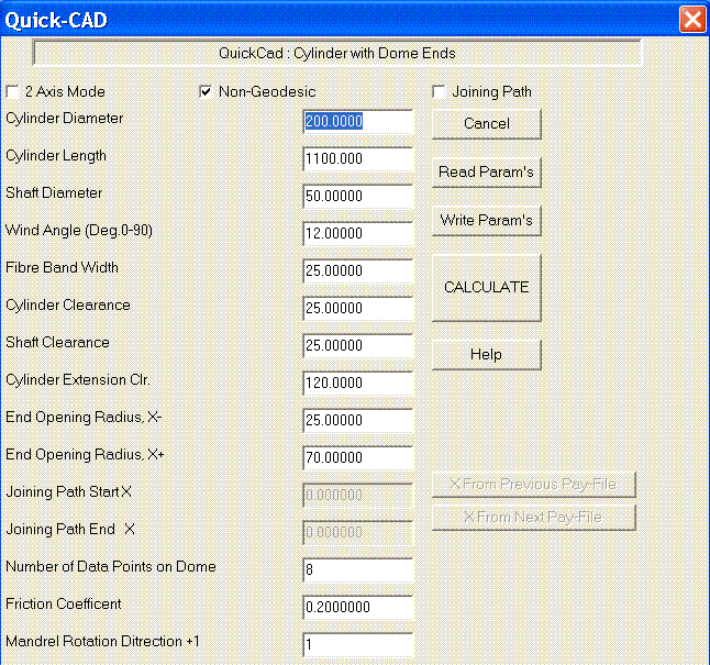
If you click on help and then Dome ended vessel in the help text, you will find a description of the parameters and a diagram link. Having entered the data, click Write Params this saves your data for if you want to re-use or change it later. For this example save it as test1.par, you can re-load the data with the Read Params option if required at a later time. When you are happy with the data click the Calculate button. The fibre path and payout path are calculated, you select the pattern from the pattern table. If you want to know more about the pattern table click on the help button. For this example we select option 1 is a 4 start band pattern. You will then automatically enter the payout viewing options.
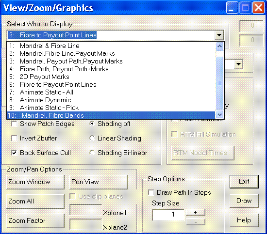
From the Payout View Menu select View Options. Then Select from the Select What to Display pull down box and pick option 10 Mandrel, Fibre Bands as shown in the picture to the below. Then click Draw.
The results should loom like the picture below after selection Yes a couple of times.
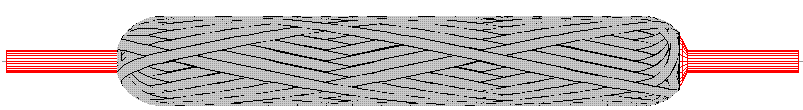
Select the View angle pull down box and pick the X- end option and then click Draw to draw this view the result should be as shown below.
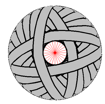
Note that the bands close up to the shaft as we selected an opening radius that matched the shaft radius. If the X+ end is viewed you can see the difference in the end opening sizes as shown below.

There are many other view options you can look at, when finished click exit and then select Finish from the Payout View Menu.
The last stage is to create the NC data. From the 'NC Post‐process' menu select 4 axis post-process and after a couple of click you have the program data to view on the screen. Note that questions asked during post-process are customer specific and items can be de-configured in not required if the items in question are not available or always standard settings on your machine
To wind this program you must have a valid post-processor configuration with the correct reference point data for the winding machine.