Maximum Speed Summary
 Cadfil Help contents
  Cadfil.com Home
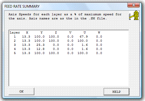
When the post-processor has finished, a summary of the maximum feed-rates for each axis for each sub-program file (SPF) is given. This looks like the picture shown below.

Feed-rate Summary Table
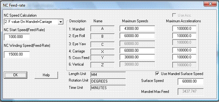
If there is only one SPF then only one 'layer' will be shown, that is, only one line of data. The titles across the top show the names that were assigned to the machine axes in the winding machine configuration file (.SM file). The values in the table show the maximum speed that each axis has at some point in that SPF. The speed is expressed as percentage of the maximum speed defined for that axis as shown in the NC feed-rate dialog (shown below). The default speed maximum values are set in the SM file.
So for layer 3 above the 'X' axis has a maxim value of 13.3% whilst the 'Y' axis has a maximum of 25.3%.
Is should be noted that any axis showing 100% indicates that the axis was requested to go over-speed and has been limited to the maximum value in the interests of safety. There is a very important point here, if for example, the user has a large and heavy mandrel the 'constant mandrel speed' feed rate option might be chosen so as not to over stress the machine. If in this case an axis has been limited at 100% then the constant mandrel speed will not have been achieved, the axes will all have been slowed at the points where over speed would have occurred. In this case it is recommended that the user post-processes again and decreases then winding speed value in the NC feed-rate dialog (shown below) so that no axis speed exceeds 99.9%.

NC Feed-rate Dialogue
Please note that for Cadfil-Pipewinder (multi-pipe) the speed is set for each SPF in the data table and should be adjusted there.
For a single SPF post process job the speed information can also be seen in the speed graph shown at the end of post-processing.