Spar Winding (Prismatic non-round sections)- DXF file requirements for cross-section.
 Cadfil Help contents
  Cadfil.com Home
The mandrel is generated from a cross section created in a external CAD program such as AutoCAD. The section is supplied in the form of a DXF file. To allow Cadfil to successfully use the DXF file some rules MUST be followed.
a) The Mandrel data is defined by a 2D profile in the X,Y plane using lines and circular arcs. Please note that circular arcs that are greater than 180 degrees should be divided into sections that are less than 180 degrees.
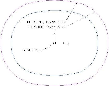
b) The axis of the mandrel should be the World Z-axis (i.e. through point 0,0) the mandrel is assumed to rotate about this axis.
c) The Lines and arcs for the mandrel MUST be joined to form a closed polyline or lwpolyline (use the AutoCAD Pedit or PE command).
d) This polyline must be on a layer called SEC and this layer should contain only one polyline but can contain other data. Note when CADFIL reads the dxf file only the first 3 letters of the layer name are considered so if the DXF file has layers multiple layers starting with SEC (e.g. SEC1, SEC22) then unpredictable results or errors may occur.
e) A clearance envelope for creating the payout path can also be created in the DXF file. The rules for creating the envelope are exactly the same as for the mandrel cross section except that the polyline for the envelope must be on a layer called SNV. In some versions of AutoCAD it is possible to offset a polyline using the OFFSET command. Thus having created a polyline for the mandrel section the envelope can be created with an all round constant clearance by offsetting it outwards, and then moving the new polyline to the SNV layer. Again only the
Cadfil has been tested on AutoCAD R12, R13, R14 & 2000, 2006 and 2008 DXF files.