IGES Interface - Importing mandrel data into Cadfil
 Cadfil Help contents
  Cadfil.com Home
Introduction
IGES is a CAD exchange format that can be output by most high-end CAD programs. Cadfil has an interface for importing data from text based IGES files as defined in the IGES 5.3 standard. Cadfil imports only a limited set of IGES entities, at this time only point data (entity type 116) is imported. There are two different scenarios, one for Axisymmetric mandrels, and one for Non-Axisymmetric mandrels.
The IGES import is selected from the IGES option on the Utilities menu, this option is only available with Cadfil-Axsym or certain options for non-axisymmetric mandrels. There are two options, importing a long section of the mandrel for axisymmetric mandrels and importing two or more planar cross-sections that form a non-round duct. Having selected the IGES option first you must select an IGES file, this is a text file of type 'name'.igs You are then asked 'Search IGES for Axisymmetric (Z=0) section?' If you answer Yes Cadfil will search for points on the plane z=0 to use as an axisymmetric mandrel profile. If you answer No, then the action 'Searching IGES for axial (YZ) sections/frames' is reported and undertaken.
Axisymmetric Mandrels
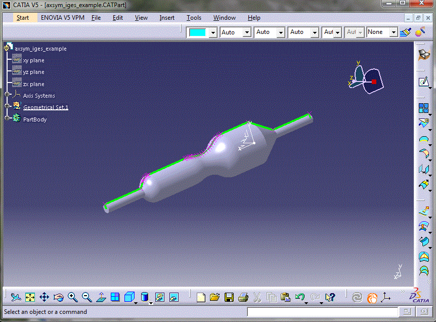
An example of a solid model created In Catia is shown in the Picture Below. Note that the axis of revolution is the global X axis which is a requirement for the IGES import into Cadfil to work correctly. If you look at the model you can see a long section from which end-points have been extracted and some intermediate points created on the curves. The IGES files axsym_iges_example.igs was created from this CAD model. This example can be found in the 'Cadfil-Install-location'\data folder. The import sequence is Pick the IGES option, Select Yes for '...Axisymmetric (Z=0)...', pick the IGES file and after some data processing you will be in a dialog to give a name for the new mandrel (.mnd) file.
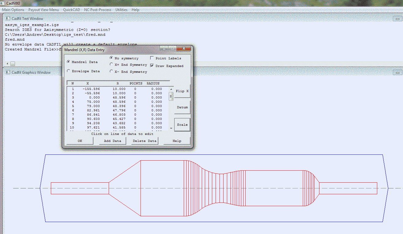
The Cadfil mandrel editor is then launched, the new mandrel can be seen in the picture below. At
this time the
envelope cannot be imported from IGES so a default envelope is created. The IGES import for axisymmetric parts has the following features:
1] Only points (IGES entity 116) are imported.
2] Only points on the Z=0 plane are imported
3] Only points with Positive (>=0) Y Value are imported as the Y value is the profile radial position.
4] If there are multiple points with the same coordinate only one of them is used.
5] The points are automatically sorted in ascending X coordinate order for the mandrel definition, the order
of the points in the IGES file does not matter.
During the IGES import a file 'cadfil_iges_import_report.txt' is created in the current working folder and is displayed after the import. The report for the example is shown below. If there are errors in the IGES file then these will be reported to this file.
 Points/Planes Summary, ***after*** duplicate points removed
 Plane Type (X=1 Y=2,Z=3) is:           3
 Plane No, Plane Value, No Points In Planes
           1  0.000000000000000E+000          37

 Points/Planes Summary, ***after*** duplicate points removed
 Plane Type (X=1 Y=2,Z=3) is:           3
 Plane No, Plane Value, No Points In Planes
           1  0.000000000000000E+000          37
 X,Y,Z,Level,Plane No
   310.0000        10.00000        0.000000        10000   1
  -155.5955        10.00000        0.000000        10000   1
  -55.59554        10.00000        0.000000        10000   1
   0.000000        48.59607        0.000000        10000   1
   100.8068        39.15764        0.000000        10000   1
   97.62092        41.58537        0.000000        10000   1
   94.20823        43.68230        0.000000        10000   1
   90.60294        45.42742        0.000000        10000   1
   86.84118        46.80322        0.000000        10000   1
   82.96066        47.79591        0.000000        10000   1
   79.00032        48.39553        0.000000        10000   1
   75.00000        48.59607        0.000000        10000   1
   149.9248        25.90958        0.000000        10000   1
   143.4080        25.12631        0.000000        10000   1
   136.8446        25.05954        0.000000        10000   1
   130.3133        25.71010        0.000000        10000   1
   123.8921        27.07020        0.000000        10000   1
   117.6578        29.12356        0.000000        10000   1
   111.6852        31.84558        0.000000        10000   1
   410.0000        10.00000        0.000000     none       1
   106.0456        35.20371        0.000000     none       1
   181.5170        31.00000        0.000000     none       1
   177.8692        30.92605        0.000000     none       1
   174.2274        30.70430        0.000000     none       1
   170.5976        30.33514        0.000000     none       1
   166.9857        29.81915        0.000000     none       1
   163.3977        29.15720        0.000000     none       1
   159.8395        28.35038        0.000000     none       1
   156.3170        27.40000        0.000000     none       1
   301.3163        21.26392        0.000000     none       1
   299.1603        23.71196        0.000000     none       1
   296.7038        25.85846        0.000000     none       1
   293.9889        27.66684        0.000000     none       1
   291.0615        29.10630        0.000000     none       1
   287.9717        30.15235        0.000000     none       1
   284.7719        30.78719        0.000000     none       1
   281.5170        31.00000        0.000000     none       1
Non-Axisymmetric Mandrels
The import sequence is to Pick the IGES option, Select No for '...Axisymmetric (Z=0)...', pick the
IGES file. The IGES import for axisymmetric parts has the following features:
1] Only points (IGES entity 116) are imported.
2] Points with the same X coordinate are grouped as being on the same plane (section)
3] Sections with only one point are ignored
4] If there are multiple points with the same coordinate only one of them is used.
5] The sections are automatically ordered in ascending X value.
6] The sections are output to a file called 'sections.mnd' in the Cadfil sections format.
7] If the sections have different numbers of points the mandrel will not be valid,
correct the original CAD data or edit the mandrel file. An error will be output to the log
file 'cadfil_iges_import_report.txt' if this happens.
8] The Cadfil sections format has a number of sections that comprise of a series of
3D coordinate points,
if there are for example 80 points on each section the first 80 points are for section 1, the second 80 points
are for section 2, on so on. Cadfil creates a mandrel that is in effect a 'ruled surface'. A surface
patch will be made from point 1 and point 2 of section 1 and point 1 and point 2 of section 2.
In general a patch is made from point i & i+1 of section n and i & i+1 of section n+1. If the points are not ordered
correctly then a correct surface will not result. There are two options for the import, dependant on a
Yes/No answer to the question 'Do you want to order the points in each section?'
If you answer No the points will be ordered in exactly the same way as they are found in the IGES for that particular section.
If you answer Yes then within each sections the points are checked and reordered such that within each section the point order is in a positive rotation (RH screw rule) about an axis parallel to the X axis that passes inside the section. This is good however it is still necessary for the software to determine which point will be point number 1 in each section. This is important in generating a valid (none twisted) mandrel topology. The method used is to find the geometric centre of the section by averaging all the section points. This centre is then the origin and point 1 is the point closest to the Positive Y axis in with Z>=0 quadrant. If this does not give the desired result it will usually be possible to open the mandrel file in a text editor and for each section 'cut' a number of lines of points from the start of a section and 'paste' them at the end of that section so that your chosen point is at the start of each section.
We did consider doing some further data processing on the IGES data to fix some of these potential errors however there are a whole number of potential issues that could arise which are best resolved in the creation of the IGES in the original CAD system. A high end CAD system is specifically designed to do such things! An example of creating data using Catia is shown below. Other CAD system may or may not have the facilities to create suitable data. Like all other things, we are open to comments or suggestions in this area.
Example making Non-Axisymmetric Mandrel using Catia
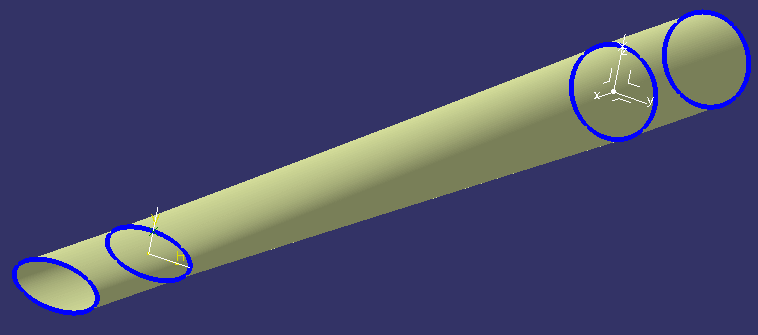
In the above picture, a mandrel model has been prepared and 4 sections created in Catia, note that the X axis in the model will be the mandrel rotation axis in Cadfil. The sections must be normal to the winding axis.
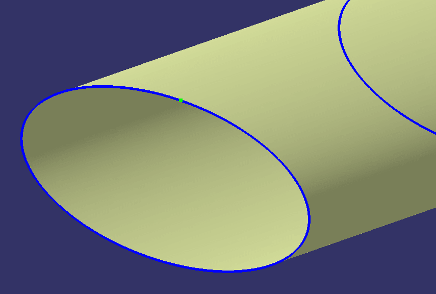
In the above picture we first created a reference point on the first section. This gives some additional control over how points are created, we set this point on the 'high' point of the shape.
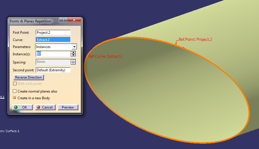
We then used the 'points and planes repetition' (GSD: Insert/Wireframe/Points & Planes Repetition) feature and selected the reference point, the section curve a set the number of points to create, in this case 80. Note the red direction arrow, we should be consistent with each section, it can be flipped with the 'reverse direction' button.
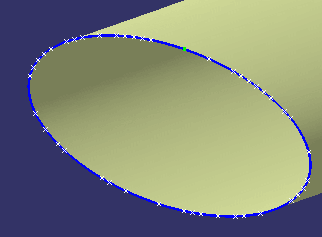
The picture above shows the points created.
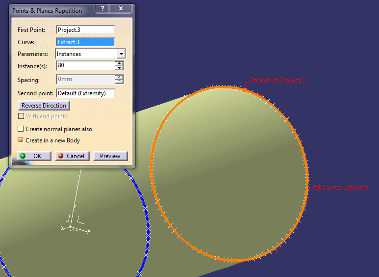
And moving on the last section having points added in the same way. There is a good chance that the points will be output in the IGES in the order in which they are created. If there is a lot of other extraneous point data in the model it might be better to copy/paste all the points created in to new empty model and to export IGES from that.

The above pictures show that mandrel after importing IGES into Cadfil. In this case we had to answer Yes to 'Do you want to order the points in each section?' because we got a distorted mandrel otherwise.