Cadfil Post Processing Strategies - Twist/Shear/Wrap (TSW)
 Cadfil Help contents
  Cadfil.com Home
Note TSW output was added to Cadfil Version 9.00 onwards
Explanation of Twist/Shear/Wrap (TSW)
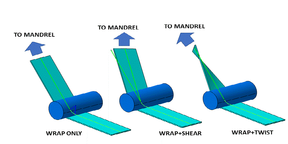
Consider the picture show below, in the left picture the filaments/tape comes from the tension/impregnation/delivery system around an exit roller/bar (the pay-out "eye" - POE) and exit to wind onto the mandrel. The angle the fibres wrap around the roller is the "Wrap angle" (W - degrees). In the middle pictures the fibres still have a wrap angle but can also be seen to deviate to the right. The angle of deviation (the difference in the green lines) we refer to as the shear angle (S - degrees). If we have shear the fibres need some mechanical restraints (e.g. a comb or friction on the bar) to stop them sliding across the roller. In the left picture you can see that on exit from the roller the 'tape' is twisted by a twist angle (T - degrees). This is because the surface of the mandrel where the tape contacts is not aligned with the roller.

Twist/Shear/Wrap(TSW) Analysis and Output
In the configuration of the post-processor "(SM file)" there are three variables @@TSW-1@@, @@TSW-2@@ and @@TSW-3@@. These can be used to output T, S and W (in degrees) for each line of motion in the NC program (you could configure it as a comment at the line ends for example). This might be useful to analyse the suitability of the program to handle the materials being used. For example with too much twist some tows may form a "rope" or a tape may fold over on itself.
Discussion of effects of TSW and Post-Processor strategies
Wrap angle has some influence on tension in the fibres. For a non-rolling bar the friction will increase as the wrap increased. Wrap can also have some effect of the spreading of tows. If there is no wrap the fibres may have more tendency to move from side to side on the roller. Wrap can be controlled to a degrees by additional rolls positions on the entry side and by use of a vertical axis (AX-6) on 6 axis machines.
Shear depends on the winding material. For individual fibre rovings that have their own tension shear can be controlled by having a "comb" or "D-ring" at the payout eye which restricts side movement, thus in this case some shear can be allowed. If there is not a comb (or similar) large shear must be avoided because the fibre will all slide to one side and bunch together. The standard Four axis post process option is designed to eliminate shear. For rigid tapes or woven tapes shear can be quite bad because the tape will crease/fold/wrinkle or in the case of 0/90 woven tapes the 90s shear and are no longer 90.
Twist also depends on the winding material. For individual fibre rovings twist tends to make the width of the band reduce and in the worst case the roving 'rope' or 'bunch' up. There is a "4 axis post process (no twist)" that used the roll (AX-2) to eliminate twist rather than shear. For rigid tapes or woven tapes twist is no so much of a problem as the tension keeps the tape flat to the roller and flat to the surface of the mandrel, the main problem is if the twist/length is too high so that the tape folds on itself.
With a 6 axis machine you can fully control T,S and W at all points in the program. The twist and shear are controlled by the roll and yaw axes (AX2/AX-3) and the wrap by the vertical (AX-6) axis. With a normal four axis machine you have only the Eye Roll axis (AX-2) so you must choose to control shear or twist, you cannot do both. Cadfil has a range of post-process control strategies to make the best use of the axes avialable on the winding machine. It is worth noting that if you are not controlling the exit position of the fibres from the roller either mechanically (e.g. comb) or by the roller orientation/tension then the movement on the eye/roller will have some influence on the accuracy of the placement of the fibres on the mandrel.