Winding using the Ring winding options
 Cadfil Help contents
  Cadfil.com Home
Introduction
There is a variation of the filament winding process where the payout eye can dispense from multiple points around the mandrel. These multiple points are normally in the form of eyes equally spaced around a ring structure. A couple of examples of such winders are shown below, it makes not conceptual difference to the process is the ring rotates or the mandrel rotates the end effect is the same. There is an option in Cadfil that is customised for such a winder. The process is the same as normal winding process except the configuration data defines the number of dispensing points (Eyes). When the pattern is selected the number of band (circuits) to make a layer based on wind angle and band width is calculated as normal. However this must be a multiple of the number of Eyes (NEYE) and if not is rounded up so that it is. The band pattern table is then calculated in a slightly different manner to reflect the fact that the laydown is simulation in NEYE locations. The fact that NEYE is greater than 1 is included in the payout (.pay) file such that the simulation of the band structure and the post-processing (number of repeats of the circuit for a layer) is automatically adjusted.
One advantage of such as systems is when the mandrel is long and slender such that the normal winding tension from a single band cause the mandrel to flex and oscillate. The ring winder can have the lateral loads balanced in different directions. In a similar way it can help with a fragile mandrel such as removable mandrels made from sand and binder or similar materials
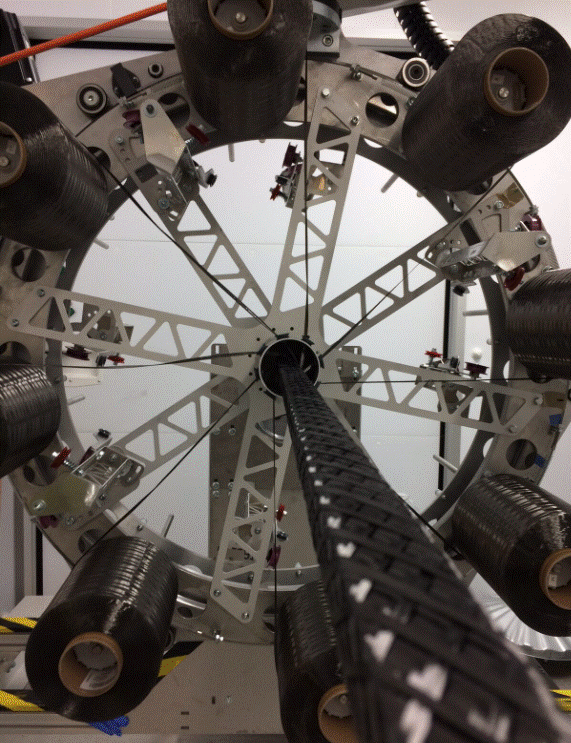
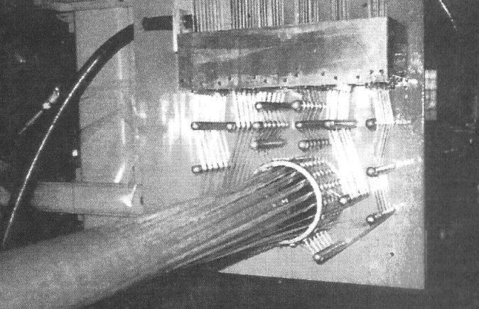
Activating the ring winding options
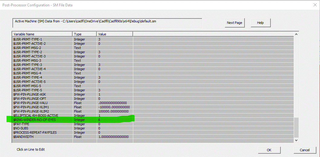
The ring winding options are activated in the SM file. This is done by setting the variable $RING-WINDER-NO-OF-EYES. If a value of 1 or less is given,or if no value is specified Cadfil will default to standard winding with 1 payout eye. If the number used is greater than 1, Cadfil will use the ring winding options with the number of payout eyes specified
Payout path creation
Fibre paths are created in Cadfil as normal. When producing the payout path, Cadfil will issue a reminder that the ring winding options are active, as well as showing the number of payout eyes. It will also round up the number of cycles to be a multiple of the number of payout eyes. In the example below, the number of cycles required for 100% coverage is 243, however there are 6 payout eyes so the actual number must be a multiple of 6. Therefore the number of cycles is rounded up to 246 (a multiple of 6)

After this, the band pattern is selected as normal. The band pattern table will show the number of payout eyes, and will also give a value for the number of skips for each option. Skips is used rather than pattern number as the normal pattern concept doesn't have much meaning. A "skip" of 5 means that the second circuit is placed 5 band spacings away from the first band from the same eye.
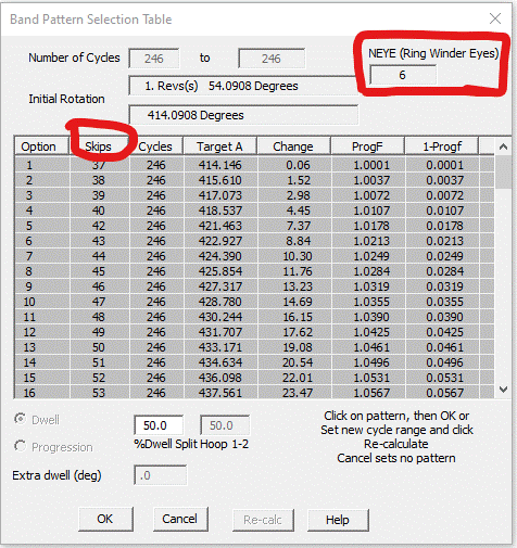
Once the band pattern is selected, the payout path can be completed.
Viewing the payout path
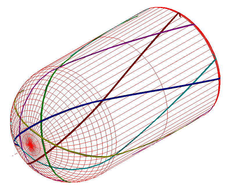
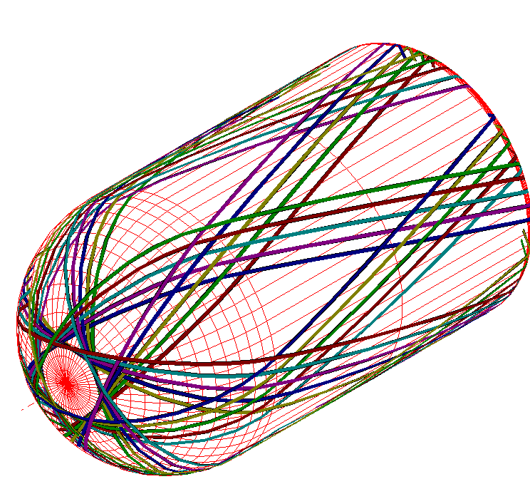
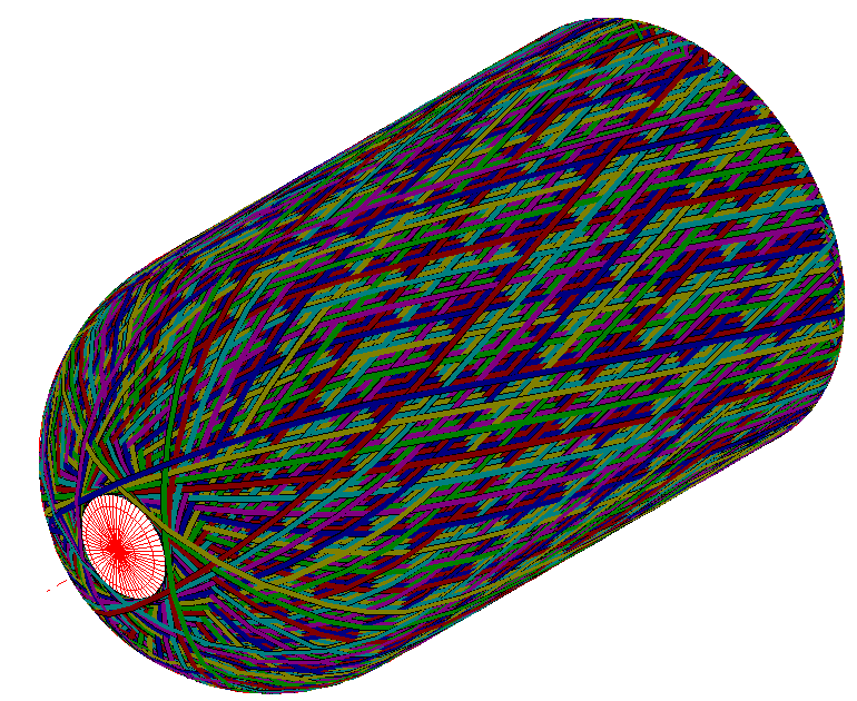
When viewing the payout path from a ring winding program, the graphics screen will show a different colour of band for each payout eye. This makes it possible to look at the same fibre band as it completes multiple circuits.
Post Processing
There is not much to not under post processing other than the number of circuits for coverage (repeats of a sub-program) will be less as it is divided by the number of eyes. It should also be pointed out that this is a 2 axis post-process as there is no eye rotation, eye yaw or indeed radial (cross-carriage) axis, only mandrel and carriage axes are available. Note that when post-processing a combined winding the user could select a mix of files some that are built for a ring winder and some that are not. If this is the case than during post-processing warning messages will be given during processing the files as clearly the resulting combined winding is unlikely to work incorrectly on a winding machine.
FEA Interfaces using Ring winder Option
The traditional approach for the fibre architecture exported for FEA analysis assumes that for axisymmetric parts the structure is a constant (averaged) for any specific cross section. Thus the different order of the band placements produced by a ring winder would yield the same FEA data a a traditional winder would. The new technology grid mapping FEA methods used in CAdfil do follow the order and positional [placement of each tow so the structure generated by a ring winder will be different to with a conventional winder. When Processing .pay file that have been created for ring winder (NEYE>1) the FEA will report that fact during the path processing.