Thickness increase and mandrel update discussion for Pressure Vessels
 Cadfil Help contents
  Cadfil.com Home
Overview
A frequently asked question relates to the subject of mandrel update. We start with a mandrel shape but after applying some winding the external shape changes. Can we continue to use the same mandrel shape for all the layers or should we redefine the mandrel shape for each new layer? This question does not have a simple answer so this topic discusses the issues and considerations. The situation with winding pipes is somewhat simpler as the thickness is only increasing in the radial direction. It is a simple matter to increase the pipe diameter for subsequent layers. The Multi-Pipe option that defines a table of layers does this automatically within the calculations. This discussion below is made using the example of a pressure vessel, a cylinder with some form of dome on each end.
Pressure Vessel Example
The picture above shows a long section of a vessel with dome end that is 400mm diameter. It has been wound with a bandwidth of 25mm using 5 tows of 12K carbon with a tow ( band ) thickness of 0.14mm. Using vessel with endcaps we created a geodesic winding of 8 degrees giving a small polar opening. The profiles in the picture show the mandrel and the wound profile after 1, 7, 13, 19 and 25 repeats of a full coverage winding program layer. For reference the profiles were created by using the "T2" table option in the Cadfil FEA data output modules, this option creates a data table and also an IGES file of the profiles. The IGES file can be read into a CAD program for model creation or analysis. As can be seen after 25 layers the cylinder has increased in radius from 200mm to 207mm and the dome has developed a pronounced "dolphin nose" that has increased the dome length by 63mm. As will be discussed in the next section this will create some winding problems.
Number of circuits on the cylinder considerations
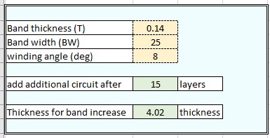
Firstly let us consider the increase in the diameter of the cylinder. We have calculated a winding program that has a specific number of circuits such that the winding creates a full coverage of the cylinder with the wind angle and bandwidth used. As the diameter increases small gaps between the band will start to appear. After a certain increase in diameter the sum of all the gaps will be greater than or equal to the width of a band so in reality the winding program needs to be recalculated so that these gaps can be filled. If you don't do that it will have a negative effect on the appearance of the winding and on the fibre volume fraction of the overall composite structure. There is a simple table shown below which is also included as an excel sheet in the Cadfil install data folder (additional_circuit_calculator.xlsx). In our example bandwidth = 25mm, band thickness = 0.14mm and the wind angle is 8 degrees. If we put those in the calculator in the Excel sheet is says that the thickness increase for an extra band is 4.02mm and that is needed after 15 layers. Without the band excel sheet using bandwidth/band thickness = 178 and the 8 degrees wind angle being between the 5 and 8 degree columns you can at a glance estimate the same value of 15 layers from the table shown below.
When Cadfil calculates a helical program, it calculates the required number of circuits to guarantee 100% coverage of the mandrel. As the radius of the mandrel increases due to the number of layers, eventually it will be possible to add an additional circuit to give the same amount of coverage again. The frequency at which the mandrel must be updated depends on the bandwidth used, the band thickness, and the winding angle. If multiple angles are used, choose the lowest winding angle. The calculation boxes above does the calculation required to give the number of layers where an additional circuit is required. This is the point at which a mandrel update is needed. The table to the above shows some pre-calculated examples comparing the winding angle to the ratio of band width to band thickness.
Consideration of end cap axial thickness
Now we will consider the thickness at the ends, the yellow profile is after 13 layers, the blue profile after 7 layers. There are a number of problems we see with this type of thickness build up. First, the mandrel is getting longer but the machine is not moving any further to the left with each layer so one effect is the band position falls short of the correct position and may then become unstable and start slipping. Another effect is the band might split so some strands slide to the inside of the dolphin nose and some to the outside. when the band splits in this way it then effects the correct band positioning through the winding path. Either way this does not lead to great winding. Visually by experience the limit will be somewhere between 7 and 13 layers, so maybe 10 would be a good choice for both the band and end build up criteria.
Having wound our 10 helical layers we now need to approximate the new shape to a standard end-cap shape. This does not have to be super accurate it just needs to reflect the general shape change. In this example we generated the mandrel in the vessel with endcaps program with a true (spherical) dome. A simple approximation in this case would be to increase the dome radius by 2mm to reflect the radius increase of the cylinder and to extend the length of the cylinder by 13mm (15-2) at each end to reflect the length increase of the dome area. We would then use these revised parameters for the next set of layers.
Different Approaches to design of the winding programs
An alternative approach using the vessel with end caps is to adjust for every layer. When you calculate a layer using this software is create a new version of the parameter file with UPD appended to the file name. You can open this, save with your name of choice (most people adopted some specific layer naming and numbering system) and use it for designing the next layer. This is a bit more work but can get confusing if you start adding and deleting extra layers in a wind sequence.
Winding very thick walled pressure vessels (for example Hydrogen tanks) with many helical and hoop layers presents the most challenging of tasks. For such a part then there is a initial design stage to optimise the layup and liner to withstand the design loads. It is often required to have several design loops at this stage. In Cadfil the FEA options accumulate the layers applying the thickness in a radial manner and as such it is entirely valid an correct to generate all the layers on a single base mandrel geometry. It is then possible to add delete, repeat layers very quickly to iterate the design via loops with the FEA analysis software. There is not requirement to complete the full winding program step of the process at this stage.
Once the initial design had been established the Cadfil FEA model can create the IGES profiles for the complete winding with all the layers and angles. It is then not too difficult a task in CAD to 'zone the thickness' such that you establish a small number of intermediate mandrel geometries in CAD. For example layers 1-15 using mandrel 1, layers 16-30 an mandrel 2....
You then parametrically re-create the paths for winding using this mandrel strategy. The FEA models can easily be regenerated for this manufacturing layup as a check if needed.