3D options dialog menu
 Cadfil Help contents
  Cadfil.com Home
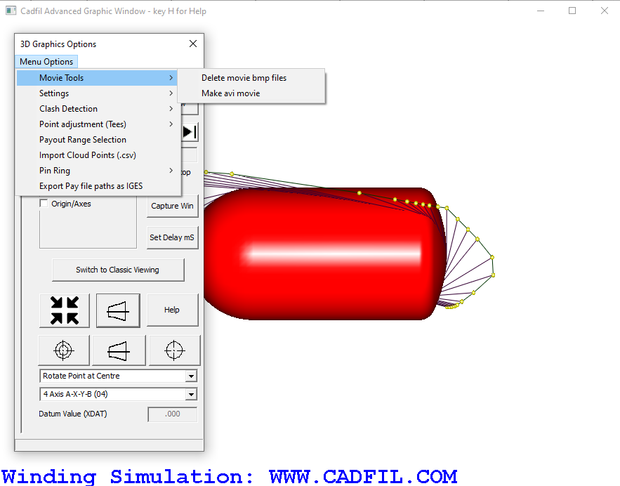
As can be seen in the screen-shot above, the 3D Dialog Box has an "Options Menu". These items are briefly described below.
Movie Tools
Delete movie bmp files This deletes all files of the pattern movxxxxxx.bmp in the current working folder where xxxxxx is a six digit number e.g.
mov000001.bmp, mov000002.bmp etc. Manually selecting and deleting these image files can be quite tedious if there are a large number of them.
Make avi movie When the "Capture window" button is pressed and then an animation is started with the "play" button each frame
of the animation is saved in the working folder as a bitmap file, the bitmap (.bmp) files are named movxxxxxx.bmp where xxxxxx is the current point number.
Non-asymmetric payout paths may have several thousand data points so a complete animation could generate a large number of files and can be slow. File
creation starts at the current payout point number so to start at the beginning position the slider on the right of the dialog to the top before selecting play.
After sufficient files have been created stop the animation with the 'Z' key, and then select this option. Cadfil does not have a movie
encoding software this is done with an external software tool. The tool that may be installed in the Cadfil install folder is ffmpeg.exe. This software is available
at https://www.ffmpeg.org/ and is
subject to GNU general public licence Version 2.0 which can be found in the following link. GNU general public licence Version 2.0.
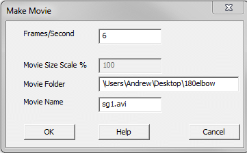
The dialog below is shown which has the frames/second, folder (for the input and
output files) and the name of the move (AVI) file to create. When OK is pressed
and assuming the example data in the dialog below the command "ffmpeg.exe -f
image 2 - framerate 6 - i \user\Andrew\Desktop\180elbow\mov%6d.bmp -y sg1.avi"
would be issued. If you want to use other options read the ffmpeg documentation
at the web site referenced above and run it manually from the command line with
your own options, or indeed use some other encoding software of your choice.
After encoding (and checking!) the movie the bmp files can be deleted as they
take up a lot of disk space.
From Cadfil version 9.53, the ffmpeg tool is no longer automatically included as part of the install file. In order to use this feature, you will need to use the ffmpeg.exe file and instructions that can be dowloaded from this page.
Settings
Select / Change Static Scene STL. This option can be used to select a 3D solid model in STL format. STL files can be exported from many 3D CAD systems. Both Binary and ASCII format stl files are supported but the file should be given a name ending in .stl. The model is used as 'background' or "STATIC SCENE' to the animation and if the Static Scene is visible (by use of the tick box associated with it) then it will be used in the head clash detection where there is a possibility of the payout head hitting part of the winding machine. A default static scene can be set in the .SM file by using $VISU-STATIC-SCENE-STL-FILE=winder_bed_type.stl The file "winder_bed_type.stl" is one of a number of example files in the Cadfil installation folder. The origin of the STL model should be such that the model X axis is in-line with the mandrel rotation axis. When this feature is used the user is asked for an XDAT value to position the mandrel origin relative to the static scene origin. Using a complex static scene can considerably slow the 3D graphics and clash detection.
Change Payout Head. This menu option can be used to select a different payout head model for use in 3D animation and clash detection. The definition of payout head models is discussed later in this help topic. Any payout head files should be named in the pattern "*payhead_def.txt" where "*" represents some unique name and these files should be saved in the Cadfil installation folder as this is where the system will first look. The payouts head file name can also be defined using the command line variable /head for example "/head myfile_payhead_def.txt". To use this command line feature edit the command line on the Cadfil short-cut on the Windows desktop or start menu.
Band Strands. This option gives you the ability to separate the graphical fibre into different numbers of band strands. A user may use this to represent the number of rovings.
Face cull on/off. This activates the openGL face cull option.
Clash detection
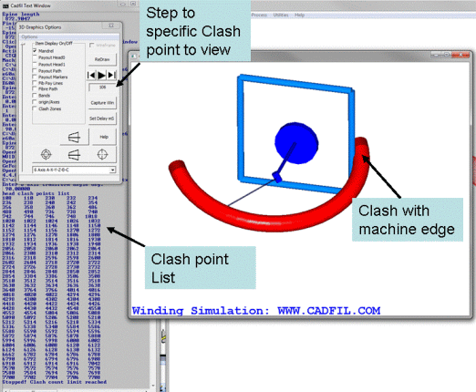
Calculate Head Clash Points This option is most useful with more complex shapes particularly with 6 axis or robot winding to check if there are any clash (crash) problems between machine and mandrel. There are a couple of things you need to do before you can use this option. Firstly you need to have defined a payout head definition that is representative of the machine geometry. This is discussed in a latter section. Secondly you need to select the post process option that is to be used from the drop down combo-box. The axes used and the control strategy of each option is discussed in the post-process sections. Remember just because there is no clash predicted using one post-process option it does not mean things will be OK with some other post-process option. Clash detection involves quite a lot of computation but the methods used are very efficient so even with large numbers of payout points, large numbers of mandrel points and a complex head geometry it should usually take a handful of seconds to complete. The button of the 3d options dialog has a progress bar that charts the progress. The longest time for calculation is where there is no clash as everything gets checked. An example of clash detection is shown below
Calculate Self Intersection
With some more complicated geometries it is possible to get self intersections these option
creates a new entity of this list of tick
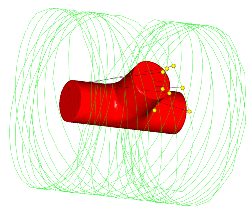
boxes that shows "Fib-Pay lines" and "Payout Markers" for any positions that generate
a path self-intersection with some other part of the mandrel. The markers are a little larger and in a different colour
but it will often be advisable to switch off the standard path and path markers so you can see these clearly if there are any. An example with a
tee winding is shown below, in this example the points shown caused the fibre to snag on the top of the T leg. To be able to wind these paths
successfully some adjustment is needed.
Point adjustment (Tees)
List Selected Points This option currently works in conjunction with the "Calculate self intersections" and prints a table in the Cadfil text window that contains the point number, the mandrel surface coordinate of the path and the corresponding payout path coordinate for all the intersection points. If the "adjust payout points" function has been used it also lists the new (adjusted) payout path coordinate.
Adjust Payout Points This allows a new position for a specified payout point number from the 'list of select points' to be calculated. The new coordinate is at 90 degrees to the direction to the next payout point in a direction normal to the plane containing the two payout positions and the fibre point position. The user can specify the distance for the adjustment, noting that positive and negative values have opposite directions. The new and old payout positions are disparaged in the graphics window and the values can be shown using 'list selected points'. At present this feature does NOT change the payout path file if you need to change this then cut and paste from the text window using a text editor is one way. Automatic update of the payout file will occur in a later version.
Apply Adjustment to PAY file . Any changes that are made can be saved to the PAY file.
Payout range selection
Payout Range Selection The Payout Path, Payout Markers & Fib Pay Lines for more complex parts e.g. elbows can often have too much information to be able to see things clearly. it is possible to enter a start and end point number so that points from say point number 100 to point number 300 only are displayed. To reset to displaying all points set the start and end to zero. The presence or not of these items can be added or removed using the tick boxes.
Import cloud points (.csv)
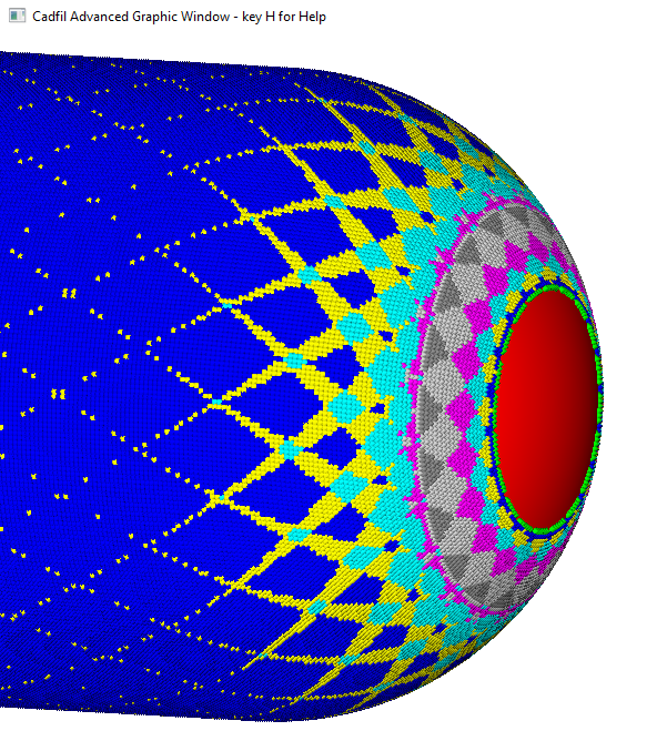
Import cloud points . This option uses data for a series of points on the mandrel surface, including ID, x,y,z coordinates, and a value for the number of bands that crosses that point. This can then display the mandrel with colour coded points that show the number of bands that cross each part of the mandrel as shown in the picture below.
Pin ring
Pin Ring file read/create. Please see the page on modelling Pin Rings in the 3D graphics windows.
Export pay file paths as IGES
Export pay file paths as IGES . This creates an IGES file which can be opened in CAD software showing the path created by the pay file.