Modelling Pin Rings in the 3D graphics windows
 Cadfil Help contents
  Cadfil.com Home
Note these features are relevant to Cadfil Version 9.57 onwards
Modelling pin rings on a cylinder
There are 2 methods for creating a pin ring model on a cylinder. The first method is to use the Cadfil dialogs to create a pin ring file. The second option is to take an existing template of a pin ring parameter file, and edit it within text editing software such as notepad to complete the parameter data. The use of pin ring models is particularly useful when winding using pin plunge.


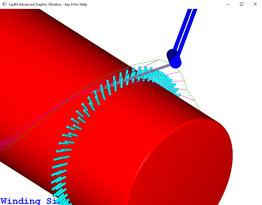
In the 3D graphics window, the pin ring models are mainly used for illustrative purposes. However if the payout head model has been correctly defined in order to replicate the shape and size of the actual payout head, this 3D model animation can be useful to see the risk of collision between the payout head, and the pins, either when the payout head is passing over the pins, or when the payout head is plunging and turning.
Creating a pin ring file
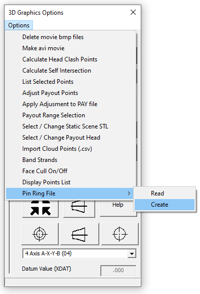
The first step is to create the cylinder payout file. This can be done in the mandrel editor, or alternatively in the pipe winding quickCAD option. In the 3D graphics window, the user can then select 'Options > pin ring file > create' as shown in the picture below

From here, Cadfil will require the input of multiple parameters through the steps listed below:
Number of pin rings
This is the number of pin rings required. This will frequently be 2 (with a pin ring either end), but could also be 4, with 2 pin rings close together at both ends.
Pin radius
This is the cross-sectional radius of one individual pin. This should be a small number in comparison to the mandrel radius or length. When the file is created, this is saved as the parameter $PRNG-RADIUS-n.
Pin height above mandrel
This is the length of one individual pin. When the file is created, this is saved as the parameter $PRNG-HEIGHT-n. The base radius of the pins, $PRNG-BASERAD-n is assumed to be the same as the cylinder radius, so that the pins are sat on the cylinder surface.
Number of pins per ring
This is the number of pins in each individual ring. In most cases, smaller cylinders will need less pins, and larger cylinders will need more. this is saved as the parameter $PRNG-NPINS-n.
Save as
The user will be asked to select a name to save the pin ring file to. Previously created files can be used by using the 'Options > pin ring file > Read' option in the 3D graphics window.
Pin rings position
This is the x position of each individual pin ring on the mandrel. This variable may be asked about multiple times. The number of x positions required is equal to the Number of pin rings specified. For n number of rings, these values are saved as the parameter $PRNG-XPOS-n.
Pins Angle stagger offset
If 2 pin rings are close together, the user may wish to rotate one of the pin rings slightly, to stagger the location of the pins so that they are not in the same rotational position. The user can input a number of degrees rotation for each pin ring. As with pin ring position, this variable will be asked about for every pin ring. For n number of rings, these values are saved as the parameter $PRNG-ANGLEOFF-n.
Editing a template pin ring parameter file
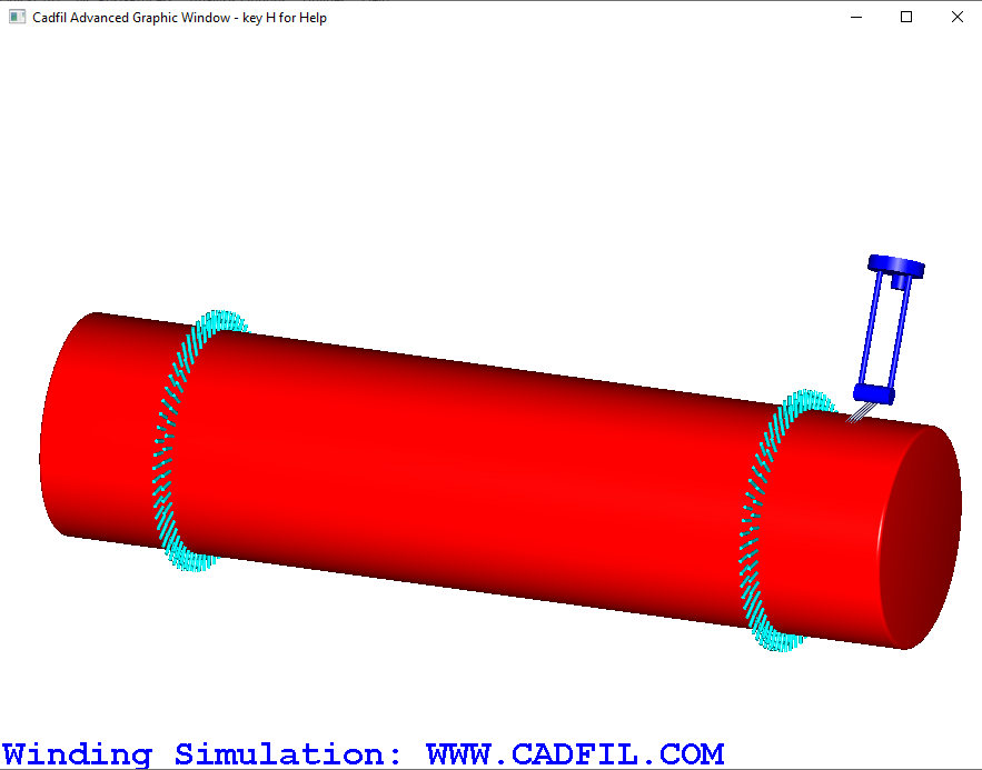
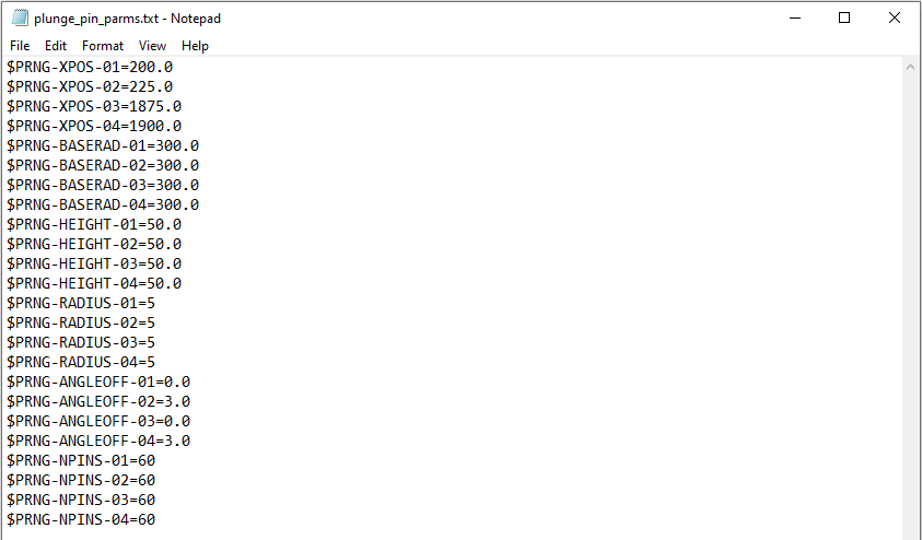
In the Cadfil install folder is a text file named plunge_pin_parms.txt. This file contains a list of parameters that allow up to any number of rings of pin models to be applied on the surface of the mandrel, however the default is 4. The contents of the file is shown below. The order of these parameters is not important, they can appear in any order. The pin rings created using the parameters shown below can be seen in the images at the top of this page.

$PRNG-XPOS-n is the X positions of the pin rings 1-4 on the mandrel. In the example shown, 1 and 2 are close together and 3 and 4 are the same. If less than 4 rings are required, x positions can be left blank. $PRNG-BASERAD-n is the radial distance from the axis in the centre of the mandrel, to the base of the pins. In most cases this value should be the same as the cylinder radius, as the base of the pin is on the cylinder surface. $PRNG-HEIGHT-n is the height of the pin ring from the base position specified previously. $PRNG-RADIUS-n is the radius of 1 pin. This should usually be a comparatively small number. $PRNG-ANGLEOFF-n can set a rotational offset to the pin ring. In the given example, rings 1 and 2 are very close, but the second ring of pins is rotated by 3 degrees about the axis in comparison to the first ring. $PRNG-NPINS-n is the number of pins in each ring. It may be that for a larger diameter mandrel, you would require a larger number of pins.
In the 3D graphics window, there is an option to select this parameter file through 'Options > Pin ring file'. This will display the previously defined pins on the mandrel surface.