Friction/Step Dialog for Fibre Path Creation
 Cadfil Help contents
  Cadfil.com Home

This dialog sets parameters for creating a fibre path to aid steering it across the mandrel surface. This has been substantially revised from 2012 onwards and has more features. To the Left we have "Geodesic", "LH Friction", "RH Friction", "Constant Angle" and "Constant Pitch". LH and RH refer to Left Hand and Right Hand. This is the direction the path will be deviated when looking along it i.e. the direction of friction when looking onto the surface of the mandrel facing in the direction in which the path is being created, thus LH friction deviates to the left and RH friction to the right as is shown in the figure below. When friction is selected the values in the friction coefficient and friction percentage become active. The larger the friction coefficient the more the path can be deviated however fibre slippage will occur if the value is not realistic. The friction percentage can be set from 0% to 100% to 0.1% resolution by type the value in the box. The actual friction used is the coefficient multiplied by the percentage. Note that when creating a path the friction status is given in the text window. Please note that Cadfil does nor 'remember' what friction was active on the paths so if you create a path with a certain value, then change the value and delete some of the path, the new value will be active if the path is advanced again
Geodesic is with no friction and is the most stable path option, on a cylinder geodesic and constant angle are the same thing. Constant Angle forces the fibre path to continue at a constant angle, this angle being the current angle. This option cannot be set on the first point of a fibre path. This option is useful for winding along mildly tapering cylinders where it would be difficult to keep progressively changing friction to maintain a wind angle. Warning: at present this option does not check the level of friction that is required to maintain the constant angle and hence if this option is used in an inappropriate manner the fibre path may not be feasible to wind due to slippage. Friction checking of this option will be available in a later version of CADFIL.

Friction Direction looking on to mandrel surface
Create/Delete Step. When the path is advanced or retreated across the mandrel surface the number of element segments the path moves is controlled by the step value, a number of preset values can be selected using this drop-down box. This can significantly speed the process of path development.
Fix Point. Pressing this button fixes (remembers) the current fibre position such that the path before this point cannot then be deleted. If it is attempted to deleted past the fixed point a warning message will be given. Clicking the Unfix Point button will then cause to software to forget the fixed point. If a point has been fixed, the path is advanced and the fix point button is pressed again the new position will become the fixed point and the previous value will be lost.
Help. The help button launch this software topic.
Action advanced the path by the current step setting using the current friction settings.
Delete retreats the path by the current step setting, you cannot delete point number 1 (the start point) or further back than a point that has been 'fixed', you need to unfix it to do this. If you need to delete the first point select the Restart Path button and you will be guided through the process of specifying the start conditions again.
Test Hoop Points outputs a summary to the text window of the X-position and radial opening for each hoop point in the winding file and is useful to determine if there are two acceptable hoop points for create a payout path or to determine the size of the end openings that have been generated.
The Stop condition can sometimes be helpful in path creation. For example, if we are creating a path along a cylinder, we are at 80 degrees wind angle and are using friction to reduce the wind angle down to 45 degrees. We could set 'step' to 1, keep clicking 'action' and watch the wind angle change in the text window output. We might get bored or risk repetitive strain injury! What we could do is set the step to 1000 (for example), click the 'Stop when angle' radio button and type '45' in the stop value box. It might also be prudent to click the 'Fix Point' button. Now when we click 'Action' the path will advance in one jump to a point where the angle is equal (or just less less than) 45 degrees. If we like the result we can click 'no stop condition' to switch this off and then carry out our next activity whatever that might be. If we decided that we want to reach that 45 degree condition in a shorter distance we could click 'delete' to take the path back to the fixed point, adjust the friction value and then click 'action' again to get a new result. In some cases using stop conditions can save a lot of time. As well as wind angle stop conditions can be set for axial (X) position along the mandrel axis.
Restart Path gives the option to save the path and then re-enter the start position and start angle. It is slightly quicker than exiting fully and having to fully restart by specifying the mandrel and the mesh parameter as well
The Finish and Save button gives the option to save the paths and then exits the dialog and Fibre Path creation, and option to proceed to the next step (payout path creation) is given. Clicking the [x] in the top right corner also selects this option, if you do not want to save the data you are given the option not to.
The View Dialog button pops the view dialog box shown below which allows the paths draw style, the mandrel orientation and many other graphical things to be changed. This stays active until the 'exit' button is selected. This dialog box is largely similar to the Dialog box used when viewing a payout path, with a few differences as explained below the picture.
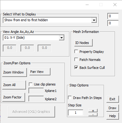
The Fibre path creation views dialog box has the following differences to the 'View payout path' dialog box:
No hidden fibre displays only the fibre path on the front surface of the mandrel. Any fibre path on the rear surface is hidden.
Hidden fibre colour changed shows the fibre path on the front surface as pink, and fibre on the rear surface as blue.
Hidden fibre dashed line is as previous, but with fibre on the rear surface shown as a dashed line.
Show from end to first hidden is a legacy option that is no longer used.
Show only path start/end points displays only the 2 points where the path starts and ends.
Draw unhidden parts of fibre as a band is the same as No hidden fibre, but showing a fibre band instead of the fibre path.