Views Menu
 Cadfil Help contents
  Cadfil.com Home
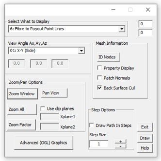
Fibre path viewing enables the user to see the fibre on the surface of the component, from any direction he desires, and permits the use to zoom in on an area of interest and pan or move the view point along the fibre. The fibre path and mandrel-viewing menu is reached, by selecting VIEWS option at the fibre path creation menu. or from the view payout path menu. The options are selection on an easy to use windows dialog box and are described as follows:
Select what to display
When a new display option is selected, the user will need to click the Draw button in order to refresh the screen.
0: Mandrel only displays just the mandrel on its own.
1: Mandrel & Fibre Line draws a single cycle of the fibre path on the mandrel.
2: Mandrel, Fibre Line, Payout Marks shows the fibre path on the mandrel surface with the payout marks outside it.
3: Mandrel, Payout Path, Payout Marks doesn't show fibre path, but shows the payout path connecting the payout marks.
4: Fibre Path, Payout Path + Marks is the same as the previous option, but also shows the fibre path on the mandrel surface
5: 2D Payout Marks shows only the payout marks but without rotation about the mandrel.
6: Fibre to Payout Point Lines displays payout marks with a line to show the path from the payout mark to the mandrel surface.
10: Mandrel & Fibre Bands shows all bands to show coverage.
Points Limits
This is at the top right hand corner of the dialog box, next to the display box. By typing the minimum limit in the top box and the maximum limit in the bottom box. When the draw button is pressed, only the points within those limits will be drawn
View angles
X-Y View This is the default view and the user sees a side profile of the mandrel looking normal to the mandrel X-Y plane.
X-Z View This is a side profile of the mandrel looking normal to the mandrel X-Z plane.
-X END This is an Y-Z view looking onto the x- end of the mandrel.
+X END This is an Y-Z view looking onto the x+ end of the mandrel.
ISO View This gives a mandrel isometric view with the mandrel axis running across the screen from bottom left to top right.
USER This permits the user to define a view direction. The system requests 3 angles to be entered (in degrees), these being the rotation of the component about its axes. The first value prompted for, is the component's rotation about the X-axis. The second value requested is the rotation of the component about its new Y-axis (this being modified due to its rotation about X). The final value requested is the required rotation about its new Z-axis. This again being modified from its original orientation by a rotation about X, and a secondary rotation about its new Y.

Zoom/Pan options
Zoom Window This allows the user to zoom in on a particular area of interest and is particularly useful with long thin mandrels as it can be difficult to see details clearly when the mandrel is fitted to the full screen. On selecting ZOOM the user must use the MOUSE to define the area of the current view that is to be fitted to the screen. The user is prompted to select two cursor positions, after entering the first point a 'rubber band' box is drawn from this location to the current cursor position indicating the area that will be selected when the second cursor position is selected. If one or both sides of the box have zero side length the zoom area will not be selected. Having successfully picked two points the software will redraw the current image, fitting the selected area to the screen.
Note that if the user picks a zoom area with no fibre or mandrel in it then the screen will be empty after redrawing! The ZOOM is reset to full screen whenever a view is selected as the VIEWS menu.
Zoom ALL This resets the zoom to full screen.
Zoom Factor Zooms based on current view centre, i.e. 0.5 halves the scale (i.e. display is smaller) and 2.0 would double the view scale.
Pan in View This allows the user to move the view position (move the mandrel across the screen) and can be useful in conjunction with the ZOOM facility. The user is requested to enter two cursor positions. The direction from point one to point two is the direction in which view point (eye) moves and the distance moved is the distance between the points. The pan view port is reset when a new view is selected.
Use clip planes shows the fibre and payout path between two x planes

Mesh information
ID Nodes is principally of use for non-axisymmetric application. When selected the use is asked for a node number (from the mesh database). If this node does not exist the system will beep. If it does exist a marker will be placed at its location on the screen
Patch Normals when this option is selected the element normal are displayed with a line from the centre of the patch that is normal to the patch surface. The outer end is marked with a marker. The markers will be re-displayed even if the view changes. If this option is selected again the feature will be switched off.

Back Surface Cull switches surface culling on or off. Culling is the automatic removal (for display) of all patches whose normal direction is away from the view direction. Can be useful for non-axisymmetric and RTM work.

Step options
Cadfil will draw the entire path by default when the Draw button is pressed. If the user wants to see the path build up, the step options allow for this. The amount of points that are added per step is controlled by the step size box, which can change values between 1 and 2,000.
Advanced (OGL) Graphics
This option opens the advanced 3D view option which allows many aspects of the fibre path and payout path to be viewed and analysed in a 3D graphical environment with dynamic zoom, pan and rotate using the mouse (ZPR mode).