Band pattern selection
 Cadfil Help contents
  Cadfil.com Home
The band pattern is used to control the final laminate structure by ensuring successive repetitions of the designed fibre path circuits are placed in the correct positions relative to each other. This usually involves making a small modification to the calculated design path by the 'progression factor' though in some cases this can be done by dwell winding where the mandrel rotates with no other motion.
The progression factor is the ratio of the desired total rotation needed to achieve a certain band pattern structure (Target Angle), to the total rotation of the generated path around the mandrel for one circuit (Actual angle).
Progression factor = Target Angle / Actual Angle
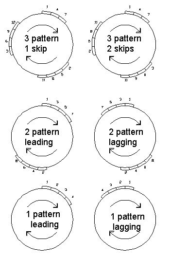
A band pattern of 1 is shown in the figures below. As can be seen, the successive bands are laid adjacent to each other. It is very unlikely for a fibre path to return to a position exactly one band-width around the mandrel from its start position. Thus, in order to achieve this, the angles of rotation of the mandrel are modified along the fibre path generated.

If the path returned 180 degrees out of phase with the start point, and if the total rotation from start to end is quite small (say 1 to 3 revolutions for example), then the modification to the path (progression factor) would be large. This would be likely to cause the path to be unstable and slip. In this example, a band pattern of 2 would be more appropriate. An example of a band pattern of 2 can also be seen in the figure above. In this case the coverage of the mandrel now progresses from two initial positions.
For band patterns higher than 2 there will often be more than one possible band structure and thus the post processor will give more than one option for a particular band pattern. An example can be seen in the figure where, a band pattern of three could be performed in two ways, the first having a 'Skip Factor' of one and the second a 'Skip Factor' of two. The other terminology used is lagging or leading referring to the band placement with respect to the direction of rotation
The band patterns that are possible are a function of the number of machine carriage circuits (cycles) that are required for one layer on the mandrel. As the number of cycles increases the number of band pattern possibilities increases.
For a given number of cycles CADFIL automatically calculate all the different band pattern possibilities, the user can then select a suitable pattern from these.
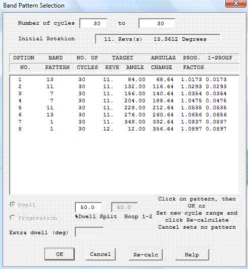
The band pattern selection figure (below) shows a typical user dialogue for band pattern selection. As can be seen, the user is first given the number of cycles and the total rotation of the path around the mandrel.

Band Pattern Selection Dialogue
The items on the table header are: The option number; The band pattern; The mandrel rotation (per cycle) that will result from selecting this pattern (target angle); The 'angular change', that is the change in mandrel rotation required to achieve this pattern; The Progression factor (PROGF); The amount by which the progression factor differs from the ideal value of 1.0.
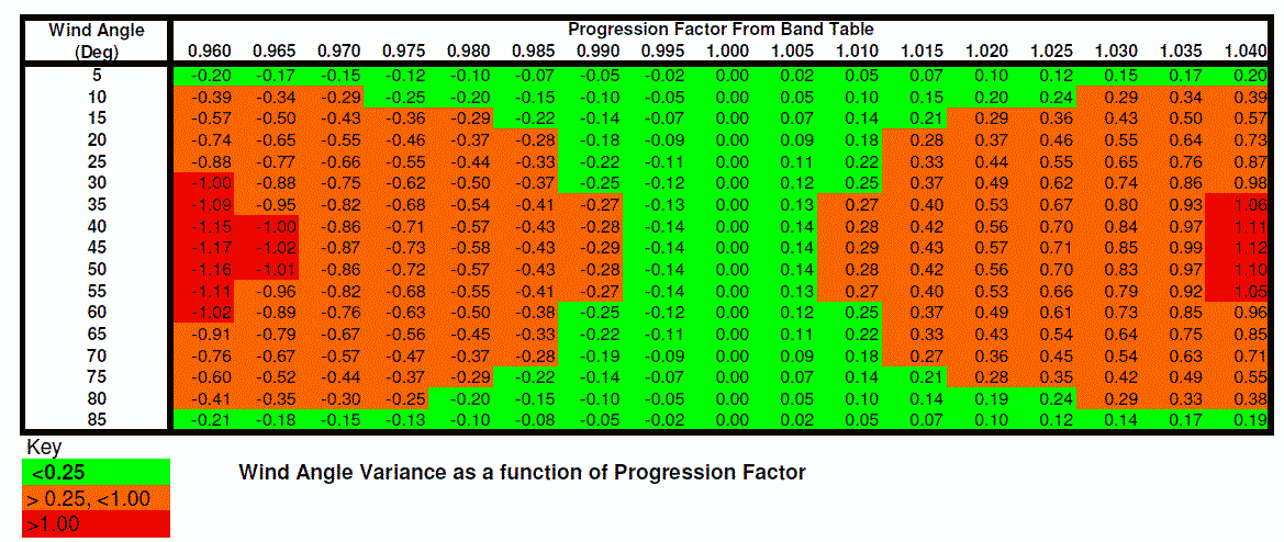
The ideal situation is to have no modification to the path, i.e. to have a progression factor of 1.000. When Cadfil suggests possible band patterns, it orders them such that option 1 is the nearest to 1.000 and option 2 is next nearest, etc. In the table below the effect of progression when winding on a cylinder is shown. For given wind angle (left most column) you can see what the effective modification to the wind angle will be for different progression values as you move across the table. The green areas show a wind angle change of less than 0.25 degrees, the red areas greater than 1.0 degrees.

If the progression factor is more than about 0.05 from 1.000 (i.e. outside the range 0.995...1.005) then fibre slip may occur. Thus such options are not recommended but may be feasible.
In the example in the dialog figure above, the user could click on line 1 for a band pattern of 13 or line 2 for a band pattern of 11.
The user may change the number of cycles to allow different patterns to be displayed and to modify thickness. For example if CADFIL calculated that 186.4 cycles where required for coverage this would be rounded to 186. The cycle range in the boxes at the top of the band table would be from 186 cycles to 186 cycles. By clicking into the boxes the user could change these values to be from 185 cycles to 187 cycle and then click the recalculate button. The best band patterns using the new data would be displayed.
The dwell split feature is discussed under the topic dwell winding .
If the cancel button is selected then no band pattern modification is applied. This should not be used for standard asymmetric CADFIL files, as the winding pattern produced will usually be random. Certain special programs (parametrics) can generate .PAY files that have the correct band pattern already built in to them and thus the band pattern modification should not be applied.