Spar Winding -Low Angle Winding Parameters
 Cadfil Help contents
  Cadfil.com Home
The SPAR winding software is found on the QuickCAD main menu (if optionally supplied). This allows the winding of non-round sections of constant or near constant section. The section should not have concave portions, as these cannot be wound successfully.
Low angle winding where the winding paths pass over the mandrel end, this is generally required for wind angles less than about 40 degrees (0 degrees being axial). The software automatically generates the mandrel geometry, the low angle geometric parameters are shown below.
Spar winding Parameters
There are three variants:
The mandrel has a flat end plate with a pin ring
The Mandrel has a idealised end-dome, this latter option has two variants with different parameters and options that might be applicable to different geometry sections for the mandrel
Click here to return to the main topic
The windows dialog below is used for the flat mandrel end with a radial pins. The winding progresses along the constant section of the mandrel at a constant wind angle the winding goes through pins at mandrel end and when the payout is at the end planes the cross feed moves inwards toward the shaft to the 'dwell hold radius'. The fibre is wrapped around the shaft and the the winding proceeds back through the pins to start the next traverse of the mandrel. There is usually a considerable build up of material around the shaft to cut away after winding.
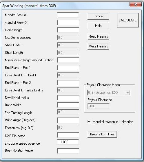
Note that of the parameters may be 'greyed' that is the user cannot select of enter data. This is because those options are not used and are retained for compatibility with different software options or for future options.
Mandrel Start X Start and Mandrel Finish X. These define the length (X finish- X start) of the winding program and where it is positioned relative to the mandrel origin (the x=0 position). The position of mandrel origin in the machine will depend on the machine datum's and the XDAT parameter described elsewhere in this help file under post-processing.
Minimum Arc length around the section, is the typical spacing of data points along the path on the mandrel surface, the units will be the same as the mandrel units usually mm or inch. For reasonably accurate winding about 8 points per rotation (for higher angles) is more than adequate, however when the user looks at the Cadfil graphics the path will appear not to be smooth. If good graphics are required use a small spacing. Please note that calculate time will be large and the data files and winding programs will be large if the spacing is small.
Dome length. Not used in this option as there is no dome. Set to zero
End Plane X position 1 & 2. These values are used for low angles winding to limit the travel of the mandrel carriage at the mandrel ends and to determine the smallest radial position the cross feed axis can move in to at the mandrel ends. Position one is at the X- end of the mandrel and position 2 is at the X+ end. If these items are greyed they are not required for the winding option chosen. WARNING the machine can move inwards and could clash with the mandrel if the planes are not positioned outside the extremes of the constant spar section.
Dwell Hold radius. The machine will move do this distance from the winding axis on the end planes whilst the fibre is wrapped around the mandrel shaft.
Bandwidth is the actual width of the fibre band to be used. This is used to calculate the number of carriage circuits required for a layer and is also used for the graphics of the banding structure.
End turning length is the distance (at both ends of the mandrel) than can be used to turn the fibre. The fibre starts at hoop and progresses down to the required winding angle. If the software can achieve the required wind angle in a shorter distance it will do so and the length of winding at the required angle will be correspondingly longer. If the length is less than that actually required a warning is given and the wind-angle that is achieved will not be the specified wind angle, the wind angle that is achieved is reported to the Cadfil text window.
Friction (coefficient) Mu is used to determine how quickly the fibre turns, a high value makes it turn faster and visa-versa. A value of about 0.2 is good for most purposes. If winding with pins on the mandrel near the ends use a very high value to turn the path quickly just outside the row of pins. Please not, Cadfil cannot defy the laws of physics, wishing for a high friction value to turn a path quickly will not make the impossible possible.
Wind angles (Degrees) , is the value in degrees that the user requires in the central portion of the wind path i.e. the total length excluding and turning zones. The Low angle option does not have a turning zone as the fibre turns on the mandrel ends thus the wind angle is fully upto the mandrel end.
Payout clearance and mode. This feature is no longer used as the clearance is always from the DXF file as this is the most general and flexible method.
Mandrel Direction check box. If ticked (default) the program is generated such that the mandrel rotates in the positive direction.
End-Zone Speed Over-ride. This options is not currently used. The function is to apply a factor to the winding speed in the turning zone.
Boss Rotation Angle. This option is not currently used in this option.