Spar Winding -Low Angle Winding Parameters- With dome-end (devt)
 Cadfil Help contents
  Cadfil.com Home
The SPAR winding software is found on the QuickCAD main menu (if optionally supplied). This allows the winding of non-round sections of constant or near constant section. The section should not have concave portions, as these cannot be wound successfully.
Click here to return to the main topic
This variant has a dome-end . The dome is considered to be elliptical in side or plan elevation blending from the mandrel section shape to the circular shaft. The only variable describing the dome geometry is dome length which is the length from the section where the mandrel start to change shape to where it meet the shaft. This length is assumed to be the same at each end of the mandrel.
The windows dialog below show the input parameters. The winding progresses along the constant section of the mandrel at a constant wind angle the winding goes around to dome going tangent to an elliptical boss than then turns back to traverse the dime to enter the constant section of the mandrel at the correct wind angle for winding the reverse part of the circuit.
The control surface for the payout clearance has been extended for this option by use of the envelope vertex described below.
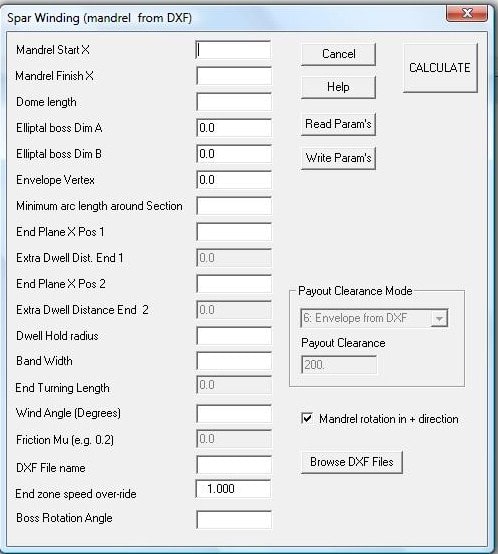
Note that of the parameters may be 'greyed' that is the user cannot select of enter data. This is because those options are not used and are retained for compatibility with different software options or for future options.
Mandrel Start X Start and Mandrel Finish X. These define the length (X finish- X start) of the constant section of the mandrel and where these sections are positioned relative to the mandrel origin (the x=0 position). The position of mandrel origin in the machine will depend on the machine datum's and the XDAT parameter described elsewhere in this help file under post-processing.
The dome length is is the length from the section where the mandrel start to change shape to where it meet the shaft. This length is assumed to be the same at each end of the mandrel.
Elliptical Boss Dim A. The elliptical boss can be used if it is more sympathetic to the section shape of the mandrel. The ellipse has a semi-major axis length of Dim A aligned with the X axis from the DXF section.. The semi-minor axis is Elliptical Boss Dim B. If required the elliptical boss can be roated relative the DXF X axis by an the Boss rotation angle (in degrees) if this is more sympathetic to the mandrel cross section shape. If DIM A and B are set the same the boss is circular.
The Envelope vertex defines a 3D clearance around the dome end. The clearance surface from the DXF file is linear between the 2 end planes. Then it becomes a conical surface with the cone base being the clearance surface on the end plane and the 'cone' vertex being on the winding axis a distance outside the end planes defined by the envelope vertex. The vertex distance would normally be longer than the dome length.
Minimum Arc length around the section, is the typical spacing of data points along the path on the mandrel surface, the units will be the same as the mandrel units usually mm or inch. For reasonably accurate winding about 8 points per rotation (for higher angles) is more than adequate, however when the user looks at the Cadfil graphics the path will appear not to be smooth. If good graphics are required use a small spacing. Please note that calculate time will be large and the data files and winding programs will be large if the spacing is small.
End Plane X position 1 & 2. These values are not used and will be greyed out.
Dwell Hold radius. not used.
Bandwidth is the actual width of the fibre band to be used. This is used to calculate the number of carriage circuits required for a layer and is also used for the graphics of the banding structure.
End turning length . Not used.
Friction (coefficient) Mu . Not used.
Wind angles (Degrees) , is the value in degrees that the user requires in the central portion of the wind path i.e. the total length excluding and turning zones. The Low angle option does not have a turning zone as the fibre turns on the mandrel ends thus the wind angle is fully up to the mandrel end.
Payout clearance and mode. This feature is no longer used as the clearance is always from the DXF file as this is the most general and flexible method.
Mandrel Direction check box. If ticked (default) the program is generated such that the mandrel rotates in the positive direction.
End-Zone Speed Over-ride. This options is not currently used. The function is to apply a factor to the winding speed in the turning zone.
Boss Rotation Angle. see the elliptical boss dimension text above for details.