Cadfil Multi-Bend Ducts(MBD) Parameter Descriptions
 Cadfil Help contents
  Cadfil.com Home
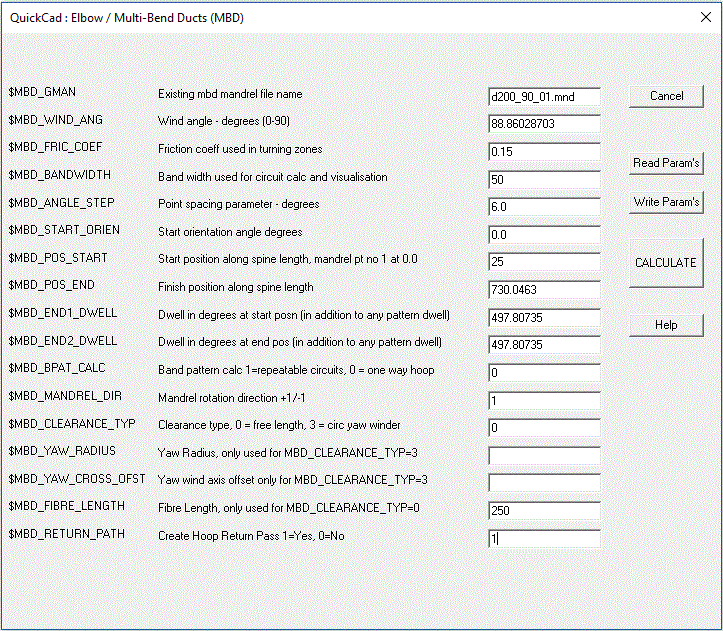
This is a sub-topic for the main help topic Cadfil Multi-Bend Ducts/Pipe Option (MBD) and gives a description of the parameters used on the dialog below.

The parameter file associated with the dialog above is show below. This is a text file so can be edited in a text editor such as Notepad or indeed prepared externally to Cadfil in a program such as Excel. The first line of the parameter file should always have the text MBDUCT as this identifies it to Cadfil as an MBD parameter file, without this there will be an error message.
MBDUCT
$MBD_GMAN=mdbex1.mnd
$MBD_GMAN=dn80x90plpl.mnd
$MBD_WIND_ANG=86.87661537             ! wind angle - degrees (0 - 90) for hoop wind_angle = atan(2*pi*r/bandwidth)
$MBD_FRIC_COEF=0.2                    ! friction coeff used in turning zones
$MBD_BANDWIDTH=12.0                   ! band width used for circuit calc and visualisation
$MBD_ANGLE_STEP=6.0                   ! point spacing parameter - degrees
$MBD_START_ORIEN=0.0                  ! start orientation angle degrees
$MBD_POS_START=50.0                   ! start position along spine length, mandrel pt no 1 at 0.0
$MBD_POS_END=1681.2389                ! finish position along spine length
$MBD_END1_DWELL=360.0                 ! dwell in degrees at start posn (in addition to any pattern dwell)
$MBD_END2_DWELL=360.0                 ! dwell in degrees at end pos (in addition to any pattern dwell)
$MBD_BPAT_CALC=0                      ! band pattern calc 1 = yes with repeatable circuit, 0 =one way/single path/hoop
$MBD_CLEARANCE_TYP=1
$MBD_YAW_RADIUS=
$MBD_YAW_CROSS_OFST=
$MBD_FIBRE_LENGTH=200.0               ! clearance - free fibre length
$MBD_MANDREL_DIR=1                    ! 1/-1 mandrel rotation direction
$MBD_RETURN_PATH=1
$MBD_GMAN
This value is the file name (without path) of the mandrel definition. This file needs to have already been created. The Mandrel (.MND) file must be in the same folder as the parameter file.
$MBD_WIND_ANG
This winding angle for the path, 90 being circumferential to the mandrel spine and zero being axial. In general low angles do not work on this type of geometry due to bridging. At the ends of the winding there is a small turning zone where the wind angle is not respected.
$MBD_FRIC_COEF
This maximum friction value is typically between 0.1-0.2 for wet winding and is used to determine the shortest length of turning zone without fibre slip.
$MBD_BANDWIDTH
The bandwidth band can be used in two ways. For $MBD_BPAT_CALC=1 we have a helical winding and the user will be asked to choose a band pattern, in this case the bandwidth is used to calculate the number of circuits to make a layer. $MBD_BPAT_CALC=0 this is a hoop winding, the winding pitch is derived from $MBD_WIND_ANG and the band width is only used for the visualisation. If you want band overlap you would need to specify an appropriate wind angle to give the band overlap needed. Wind-angle = arctan( pi * pipe-diameter / pitch ).
$MBD_ANGLE_STEP
This value is typically between 6 and 60 degrees and determines the number of points in the .PAY file created. With 6 degrees there are 60 points per rotation and with 60 degrees there are 6 points per rotation. With less points the path (and also visualisations)are less accurate but depending on the machine more (or in some cases less) points may give a smoother motion. A user may be forced to have less points if the CNC memory is limited in size though this is unlikely to be the case with most modern CNC systems.
$MBD_START_ORIEN
A normal value is zero which means the path on the mandrel surface will start at the top of the circle of the pipe section. In some cases a rotation position can be specified here so that the start position matches with the finish position of a previous winding. Note that for hoop winding ( $MBD_BPAT_CALC=0 ) where we also have the return path back to the start position ($MBD_RETURN_PATH=1 - a double layer) then the end orienation automatically matches the start orientation as the path is made to be a whole multiple of 360 degrees. This type of path is automatically repeatable with no further consideration needed.
$MBD_POS_START
MBD is a form of pipe winding it is just the the pipe is not straight. Distance along the pipe is measured alone the curved spine from the first end defined (position 0.0) in the mandrel to the far end. This parameter is the start distance from the fisrt end. Note that we program the band centre position so starting half a bandwidth from the might end might we desirable in many cases.
$MBD_POS_END
The end position is the distance along the pipe is measured alone the curved spine from the first end defined in the mandrel to the far end. Where a symmetric winding is needed the user would want to know the total length of the spine (SPINE-LEN) so that if $MBD_POS_START=50 then $MBD_POS_END = SPINE-LEN - 50. When you calculate in the MBD option the spine length is output into the cadfil text window if you need to know that value.
$MBD_END1_DWELL
Some additional rotation can be added at the turning (end points) for example with hoop winding a 360 rotation is often added at the end to give a straight edge.
$MBD_END2_DWELL
Some additional rotation can be added at the turning (end points) for example with hoop winding a 360 rotation is often added at the end to give a straight edge.
$MBD_BPAT_CALC
This takes the values 1 or 0. For $MBD_BPAT_CALC=1 we have a helical winding and the user will be asked to choose a band pattern, in this case the bandwidth is used to calculate the number of circuits to make a layer. $MBD_BPAT_CALC=0 is a hoop winding, the winding pitch is derived from $MBD_WIND_ANG and the band width is only used for the visualisation. Note also the $MBD_RETURN_PATH=1 value which can be used with $MBD_BPAT_CALC=0 to included the return path.
$MBD_CLEARANCE_TYP
This controls how the clearance is specified in creating the .PAY file. Currently there are there possible values 0, 3 and 4.
$MBD_CLEARANCE_TYP=0 is the normal value, this sets a constant length of fibre beween mandrel and payout eye. The length
is specified using $MBD_FIBRE_LENGTH.
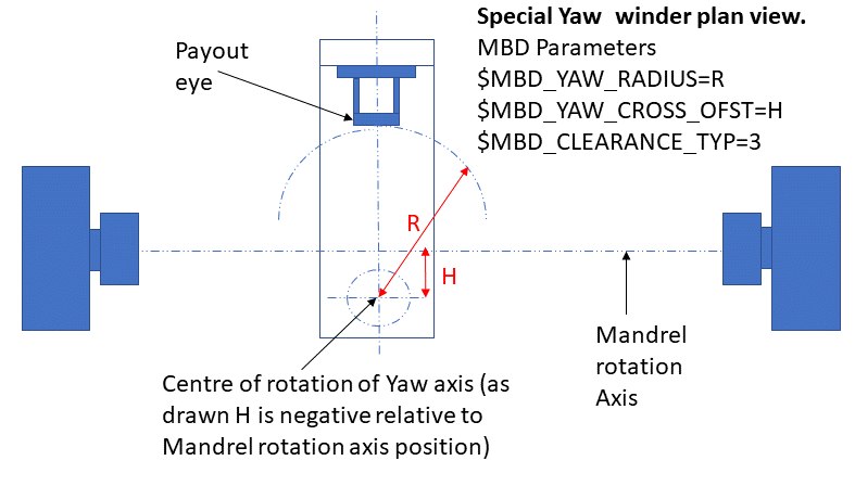
$MBD_CLEARANCE_TYP=3 is for a special winding machine axis configuration known as a "Yaw Winder", this uses parameters $MBD_YAW_RADIUS
and $MBD_YAW_CROSS_OFST which must be set.
$MBD_CLEARANCE_TYP=4 sets a spherical claerance, the centre of the sphere is at the mandrel origin and the radius is given by $MBD_YAW_RADIUS.
$MBD_YAW_RADIUS
This is used for $MBD_CLEARANCE_TYP=3 or 4. see the notes above under the $MBD_CLEARANCE_TYP heading. For TYP=3 the yaw winder figure below shows the definition of this parameter.
$MBD_YAW_CROSS_OFST
This is used for $MBD_CLEARANCE_TYP=3 the yaw winder figure below shows the definition of this parameter.
$MBD_FIBRE_LENGTH
This sets a constant length of fibre beween mandrel and payout eye used with $MBD_CLEARANCE_TYP=0 only
$MBD_MANDREL_DIR
This parameter takes the values +1 or -1 and determines the direction of rotation of the fibre path and hence the winding machine. +1 is the normal case.
$MBD_RETURN_PATH
This takes values 0 or 1. Note that for hoop winding ( $MBD_BPAT_CALC=0 ) we can set $MBD_RETURN_PATH=1 to calcualte the reurn path back to the start position to make a double layer. The end orienation autommatically matches the start orientation as the path is made to be a whole multiple of 360 degrees. this type of path is automatically repeatable with no further consideration needed.

It is also worth noting that for a helical winding with $MBD_BPAT_CALC=1 (i.e. one that uses the band pattern table), the number of circuits is calculated to cover the mandrel based on the 'centre line' of the pipe. This means if the true (actual) band width has been entered there will be gaps on the outside of the bend and overlaps on the insides of the bends. If the bend radius (on the centre line) is R and the pipe radius is r then to cover the outside the bandwidth would be needs to be a factor F times wider for no gaps where F =(R+r)/R. If you need to gaps there are two methods of adjustment either make the band width you specify in the parameters smaller i.e. use BW/F or in the band pattern selection table increase the number of circuits by a factor of F. The former puts the data in the .par file which means you can't later get it wrong by forgetting to adjust the number of bands but it does mean that when you run the simulation you will still see band gaps as you are using a 'fake' reduced bandwidth rather than the real one. The adjusted circuits method will give the band appearance in the simulation that you will actually get when you wind as it is using the true band width.
For Hoop winding you would set the band pattern calculation parameter to zero. If you also wanted a double layer (along the mandrel and then back to the start) set the repetable circuit parameter to 1. Please note that, as of vertion 9.26 the software will automatically add some aditional dwell at the end (if required) to ensure the winding finishes with the mandrel at the same orientation as the start. This way the hoop layer can be directly wound repeatedly without any joining path being needed. The amount of additional dwell is reported to the Cadfil text window. Along with the total rotation for the winding and total less any whole rotations (modulo 360). For a repeatable circuit the module 360 value should always be zero.
[an error occurred while processing this directive]