Cadfil Pipe (Double) Reducer (QuickCAD)
 Cadfil Help contents
  Cadfil.com Home
Note these features are relevant to Cadfil Version 9.07 on onwards
Introduction
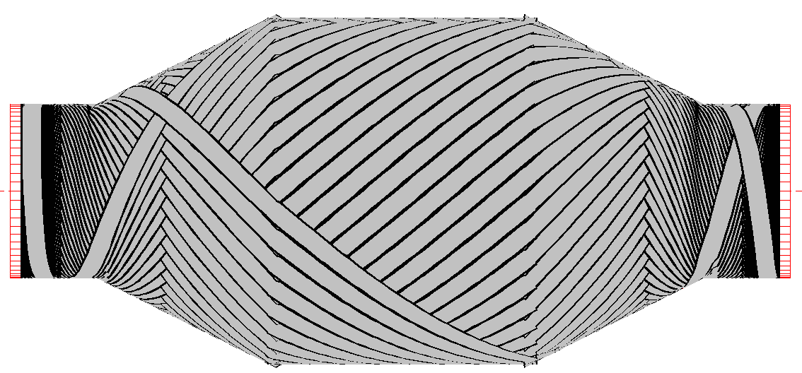
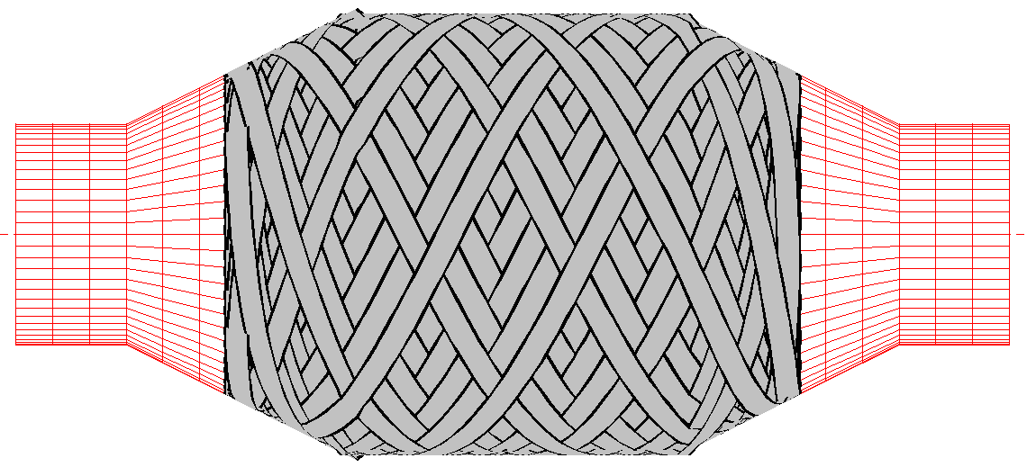
This Software option can be used for winding the Pipe fitting known as a reducer which is used for joining pipes that are of a different diameter. By far the most efficient way to wind such a part is to make two parts 'back to back' that are then cut in the middle to remove from the mandrel. The mandrel is normally made with a cutting groove at the centre. Making a double reducer eliminates the large amount of waste material that would be needed to do a "pipe friction turn" on the larger diameter. These reducer geometries and other alternative reducer geometries can also be made using the interactive Cadfil Axsym package. There are two types of wind program that can be made, shown in the two pictures below. A "full wind" where we wind on both the large and small diameter pipes and a "part wind" where we wind on the large diameter and part of the cones. A user might want to use both types to better optimise thickness and winding angle for the part. If the full wind were used alone, the small diameter pipe would be substantially thicker than the large diameter pipe, where considerations of stress analysis would want it the other way around. The way the user chooses between these two types is only by the specification of the axial distance of the turning position "WL" measured from the mandrel centre. LW will end on the cone portion or on the small diameter pipe. The centre of the mandrel is also the zero or datum position of these mandrels.


Reducer Input Parameters
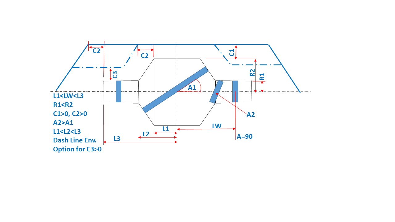
The figure below shows the input parameters for the winding which consists of a number of dimensions and the winding angles (degrees) on the two diameters. The winding angle on the small diameter is not actually used if it is a partial wind. C1 and C2 define the blue envelope lines which is where the machine will be constrained to place the fibre payout eye. If C3 is none zero the dashed part of the envelope is defined, this allows the machine to run closer to the mandrel on the small dianmeter area if closer control is needed. The C3 parameter was an addition at V9.17. In general it will be possible to wind with a 2 axis winder particularly if C2 is long such that no machine positions are generated on the conical parts of the envelope. This can be checked in the payout viewing options later in the process. The winding program creation process is to enter the parameters in the windows dialog shown below and then click the "Calculate" button. The data is saved in a parameter (.par) file and checked for errors. If there are data errors these are reported in the cadfil text window and the user is returned to the dialog to correct them. If the data is OK payout path viewing will be launched and the band structure (like in the pictures above) will be displayed. The user might be asked for a band pattern selection from the band pattern table if the "Manual" band pattern option has been selected. The band pattern table and selection is described in the elsewhere in help system (follow the link). Having exited from payout path viewing the payout file (.pay) created can be post-process to make a winding program or it can be added to a list of payout files using the "combine Programs Option", this list can later be post-processed for a multi-layer wind program. The mandrel (.mnd) payout files take the same name as the name you select for the parameter (.par) file.

Reducer Input Dialog
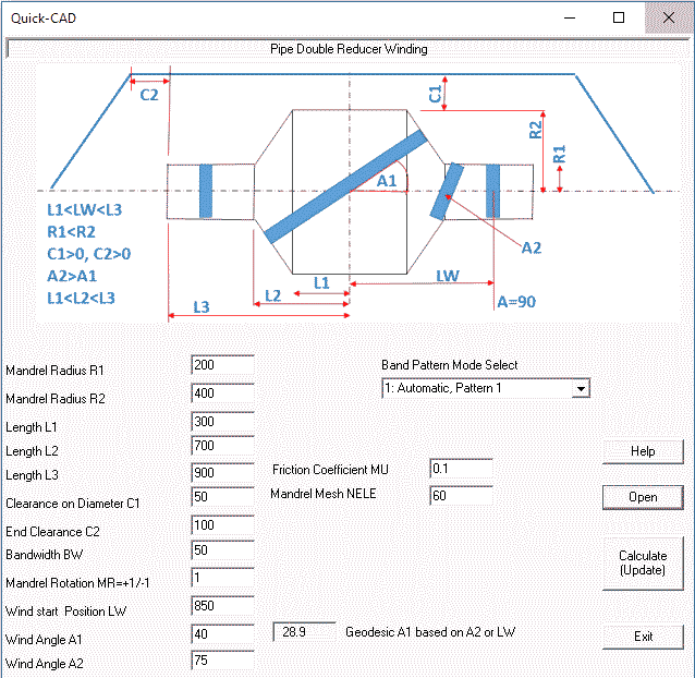
The reducer Option is controlled through a single Windows Dialog which is shown below. The Geometric parameters need little further explanation other than the diagram. If any of these are zero or negative an error will occur and there are also many other obvious error conditions. For example if L1>L2 (L1 is greater than L2). In all such cases error messages are written to the Cadfil text window. The Friction Coefficient is used for the turning zone on the small diameter pipe for the full wind case and on the cone portion for the part wind case. A default value is supplied but the user can specify another value if required. A larger friction value will give a shorter turning zone (or more angle variation possibilities) but a value that is greater than reality will just cause the fibres to slip when winding. For normal wet winding stick with the default value. NELE is the mandrel meshing parameter, again a default is supplied and there is no reason for a user to change this. The Open button can be used to read parameter data that has previously been entered and saved. The Calculate button saves the data, checks the data and if it is good calculated the winding program. The Exit button or the [X] quits without saving. Help opens this help topic. Follow the link for more information on band pattern .
Limitations of wind angle
The laws of physics apply! Cadfil cannot do things that are not physically possible. Some useful points to consider follow. The angle "A2" will typically be a high wind angle between 55-85 degrees as it is constrained by two factors. Firstly, the lower the angle the longer the turning zone, so it may not be possible to achieve a low angle in the length given (LW-L2). Secondly, if the cone is steep then if you do not cross from the small diameter onto the cone at quite a high angle the fibre will just bridge across the surface. As the path travels up the cone due to the geodesic principal the fibre angle will become lower. There is a 'natural' geodesic wind angle A1 resulting from the values of A2,R1 and R2 and after the calculation this natural angle is displayed in read only the box marked "Geodesic A1 based of A2 or LW". If your A1 requested is a long way from this value it it likely the calculation will fail because there is not enough friction available. You will be informed of this in the text window and/or pop up error messages. Similarly for the part wind case, for a given start position LW on the cone there will be a natural angle A1. In this case it depends what is important to you, the thickness and extent of coverage an the cone or the wind angle on the large diameter. Remember your optimum fibre structures may be achieved by having several layers that are different. This Cadfil module creates winding programs it does not design the component.
