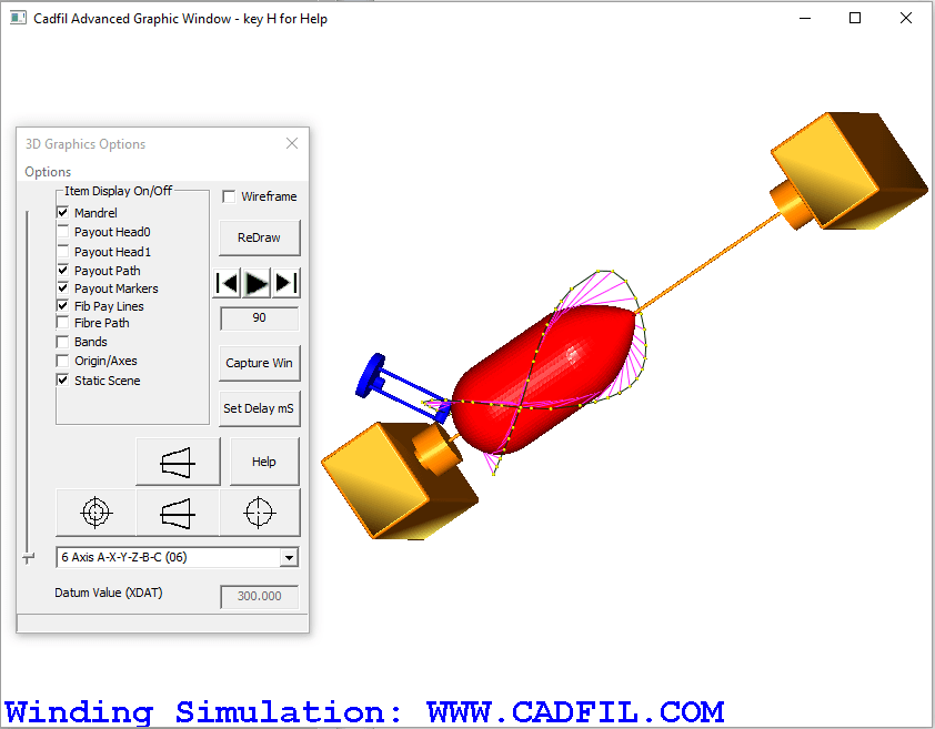
Cadfil Simulation with Static Scene added
 Cadfil Help contents
  Cadfil.com Home
Note these features are relevant to Cadfil Version 9.04 on onwards
The Advanced graphics functions allow many aspects of the fibre path and payout path to be viewed and analysed in a 3D graphical environment with dynamic zoom, pan and rotate using the mouse (ZPR mode). If you are not familiar with these functions then follow this link. With more complex machines with 6 axes and particularly when using 6 axis robots it can be important to understand problems of obstructions that are in the region of the mandrel such as the machine headstock or tail stock. These can be modelled in a 3D CAD system outside cadfil and then imported via a STL file. The user can run the 3D motion of the machine and visually assess any clearance issues. It is also possible to include the static scene model in the clash detection calculations. At this time Cadfil only supports text (ASCII) STL files not binary form STL files. Obviously for the purpose of simulation only simplified models are needed every nut bolt and fillet radius would be far too much detail. The origin (0,0,0) position of the STL file in CAD should be on the mandrel rotation axis and the X direction should be that of the machine carriage and the Y direction that of the machine cross feed direction (normally with Z up). I would normally recommend setting 0,0,0 at the face of the chuck on the rotation axis. The "X" position of the STL can be adjusted relative to the mandrel by use of the XDAT value (common with post-processing) requested when you start the payout view option with $VISU-STATIC-SCENE-STL-FILE set in the SM file.
The picture below shows the head and tail stock modelled and imported as an STL file. To use this feature we added the line $VISU-STATIC-SCENE-STL-FILE=simple_head_stock.stl to the ".SM" winding machine configuration file. You can call the STL file whatever you wish after the "=". You can see that in the 6 axis wind mode chosen the machine head comes very close to the headstock and it is clear it would be better if the mandrel was positioned more to the right using the XDAT offset.
Some sample STL files are included in the Cadfil install folder.

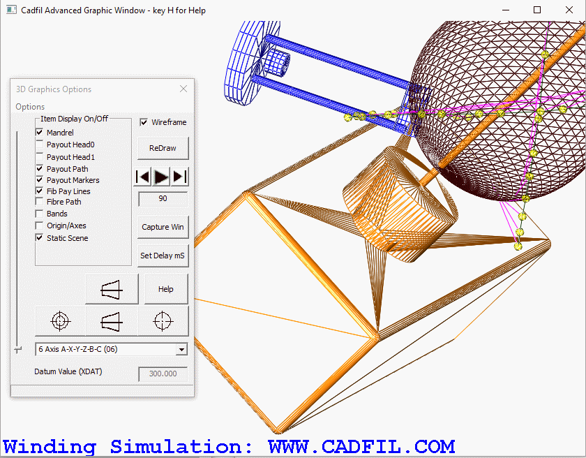
Below we show the headstock with the wire-frame box ticked on the dialog. You can see that the STL file is made up of triangles. You may or may not be able to control the number and size of these triangles in the CAD system used to generate the STL file. Bigger STL files will make the graphics slower and at some point and error will be given if there is not enough memory or system resources available on the PC. You can also see on the dialog that a "static scene" tick box has been generated to allow the user to switch the static scene On or off on this display.
