Payout Path Viewing - Cadfil Advanced Graphics Window
 Cadfil Help contents
  Cadfil.com Home
Note these features are relevant to Cadfil Version 9.00 on onwards and some of the earlier beta versions (8.5x)
Introduction
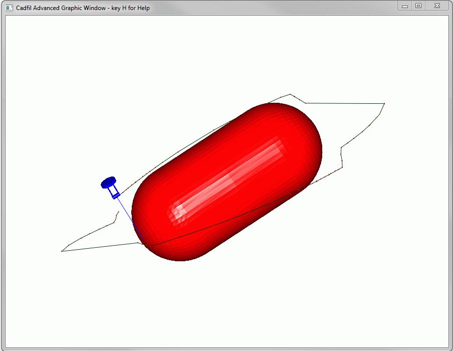
The Advanced graphics functions allow many aspects of the fibre path and payout path to be viewed and analysed in a 3D graphical environment with dynamic zoom, pan and rotate using the mouse (ZPR mode). 3D animations of the machine and mandrel motions can be seen both in dynamic and step by step modes. Is is also possible to make 3D movie files(.avi) to share with others. Other function include advanced clash detection and self intersection detection. Self intersection can occur on complex geometries such as T's where there is no machine clash but the fibre between mandrel and payout eye interferes or snags on some other part of the mandrel. Please read the section on Hotkeys below it is not uncommon for users to miss this detail and then get stuck in the animation without being able to stop. These 3D graphics display options use the OpenGL graphics systems. To use OpenGL graphics the Windows PC must have a graphics card with OpenGL (OGL) support. Even very basic 'integrated' graphics systems on modern PC's have basic OpenGL support via emulation. For best performance however (speed of redraw) with dynamic graphics a "3D Graphics" card is the best option. Nearly all modern 3D graphics cards will have OGL support however the speed and capabilities can vary enormously. The advanced graphics options are switched on or off using the "OpenGL" menu option on the Utilities menu. The current default is to be off. The advanced viewing functions currently all relate top the "View Payout Path" options. When these options are entered the graphics capability is displayed the Cadfil text window, as exampled below.
  OpenGL Vendor: NVIDIA Corporation
  OpenGL Renderer: GeForce GT 525M/PCI/SSE2
  OpenGL Version: 4.1.0
It is also possible to add static parts of the machine for example the headstock by adding a 3D external STL file for information on this follow this link on "Cadfil Simulation with Static Scene added".

Hotkeys: H,Q,Z,P
Options for controlling the Graphics Window output can be set using the options dialog shown below. there are also a number of 'hot-keys' which
if pressed when the mouse cursor is over the Graphics window perform certain actions. Please note when viewing a 3D animation that is running in the
continuous mode the only way to stop this is to hover the mouse over the graphics window and hit one of the Z, P or Q hot-keys, Z being the best choice.
Key press H or h > Opens the help system
Key press Q or q > Closes the advanced graphics window
Key press Z or z > changes into the ZPR - Zoom/Pan/Rotate mode (see below)
Key press P or p > changes into the Pick Mode (see below)
In ZPR (Zoom Pan Rotate mode ) holding the Left Mouse button down whilst moving the mouse causes rotation of
the scene, vertical, horizontal and circular mouse motions rotate about different axes. Holding the middle
mouse (or scroll) button down whist having the mouse up or down the screen zooms the scene in and out. Holding
the Right Mouse button down whilst moving the mouse repositions (pans) the scene.

3D Option Dialog
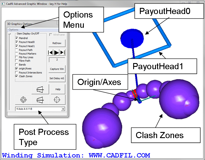
The choices on the 3D Options Dialog are shown the the picture above and are described here.
The Tick Boxes
The Tick boxes determine what will be part of the displayed in the next redraw.
The options that you see in your might be slightly different to those shown as items can be added or removed from the list by using different Cadfil functions.
The tick box items shown are briefly described below:
Mandrel - Includes the shaded mandrel mesh in the view.
PayoutHead0 and PayoutHead1 - Are included to allow verification of the machine head definition that is being used.
The payout head is a collection of cylindrical solid objects that defines some key aspects of the machine head geometry.
The group PayoutHead0 are objects that are subject to both Yaw and Roll axis rotations (Cadfil axes 2 and 3).
The group PayoutHead1 are objects that are subject to only Roll axis rotations. These options draw the head geometry in the
position and orientation that it has been defined. You might not be able to see it if it is inside the mandrel! Try turning the mandrel off.
Normally these tick boxes would be un-ticked (off).
Payout Path - The path in 3d space the payout eye will travel.
Payout Markers - This puts a small coloured solid sphere at all the actual points that make up the Payout path.
Fib Pay Lines - This drays lines that connect to fibre position on the mandrel surface to the corresponding payout path position.
Fibre Path - The path of the fibre on the mandrel surface.
Bands - This shows the structure of the final winding on the surface of the mandrel using the actual programmed width of the fibre band.
Please note that for technical reasons the old "Bands views" in the non-OpenGL payout viewing can often 'look better'.
Payout Intersections - This shows "Fib-Pay lines" and "Payout Markers" for any positions that generate
a path intersection with some other part of the mandrel. The markers are a little larger and in a different colour
but it will often be advisable to switch off the standard path and markers so you can see these clearly if there are any.
Origin/Axes Shows some 3D arrows that denote the XYZ axes and the Origin (zero position) of the mandrel and payout head definition.
Note that the axes may be obscured by the mandrel if they are inside it!
Clash Zones These are the purple spheres shown in the picture above. To make clash detection more effectiveness Cadfil creates
a number of spherical zones that contain a sub-set of the mandrel vertices and then applies the principal that if there is no clash
with the sphere then there is no need to look at a clash with any of the objects contained within it. Normally there is no need/reason
to have these entities visible other than a quick check to see if the zones make sense.
3D Option Dialog Buttons
There are a number of buttons on the dialog that are briefly described in this section. There are 4 pre-set view icon buttons top/side/left/right that change the view direction and redraw the display. The set delay allows a pause to be set (in milliseconds) between screen updates during animation if it is too fast. The Redraw button causes the display to be updated, useful after changing the tick box selection. The Capture Win button causes the graphics window to be saved a a Bitmap file, click this button and then the redraw button to capture the window, the 'Capture' is switched off after the bitmap is created. The bitmap is created in the current working folder and is called "img000001.bmp". If the animate (Play) button is pressed then each frame of the animation is saved as mov000001.bmp, mov000002.bmp etc. This continues until the animation is stopped by pressing the Z key. Please refer to the section on Creating a Movie file for more detail on this. The "Step Back", "Play" and "Step forward" icon buttons are used to animate the movement of mandrel and payout head in continuous and step mode and are discussed in the 3D Animation section.
3D Options Dialog Menu

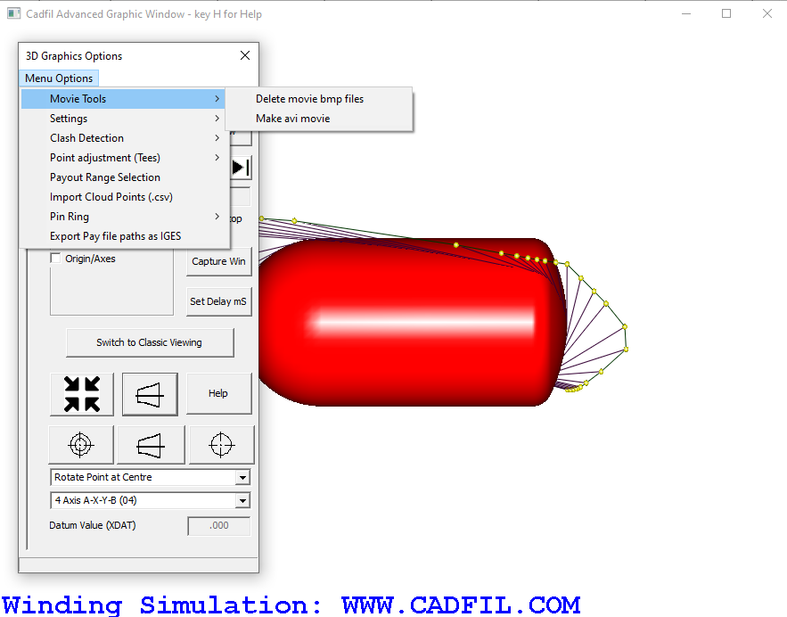
The options menu is a drop down list that allows the user to access different options within the 3D graphics window. These options are discussed on the 3D options dialog menu page.
3D Animation
There are numerous animation option where a simulation of the machine motion can be made. Referring to the figure above, there is a combination (drop down) box where you can pick all the same post-process options you can find on the NC-Post Process menu so you can simulate specific options. The speed of the animation depends on the complexity of the mandrel and payout head definitions the number and spacing of the payout points and of course the performance of the computer and graphics card. In many cases the animation may be too fast. Suspend the animation by hitting the 'Z' key with the mouse over the graphics window. Then click the "Set Delay" button. This allows the entry of a delay (in milliseconds) between position updates. A value of 200 is 0.2seconds, the default is 0. Resume the animation by clicking the "Play" button. Use the Pre-set view buttons to view from standard view (top, side etc) or use the dynamic Zoom, Pan, Rotate by moving the mouse over the graphics window with left, middle/wheel or right buttons held down. You might note the 'slider' on the side which shows the progress of the winding (it wraps back to the start when the end is reached). When the animation is cause you can drag this position to set where the animation will restart on Play. The step forward/backwards icon button allow you step forward and backwards in the animation to view particular positions in ZPR mode.
Defining the Payout Head geometry for 3D Animation
Making a payout eye/head that mimics the size of that used on the machine gives a more useful simulation. For more information see the custom payout head page.