Tee Piece Winding: Payout Path
 Cadfil Help contents
  Cadfil.com Home
In a previous sections the creation of a fibre paths for Tees is described. In this section the create of the 3D machine path (payout path) is described. After saving a fibre path you can proceed to the 'Create Payout Path' option when prompted. Alternative a payout path (.PAY) files can be created from a .FIB file at any time by using the 'Create Payout Path' option from the Cadfil Main menu.
The steps are simple:
1] Selected the 'Create Payout Path' option from the Cadfil Main menu.
2] Selected a fibre path (.FIB) to process.
3] Some filtering of the paths data is then undertaken this does two things, it deactivates data points that are very close together (the tolerance is set automatically based on the mandrel size parameters) and is eliminates any points around the tee blend where there is liftoff (bridging). Such point cause the mandrel motion to be erratic. Please note where liftoff is indicated the fibres will not be tight to the mandrel surface and may require some consolidation after winding. The view below indicates where lift off points have been identified.
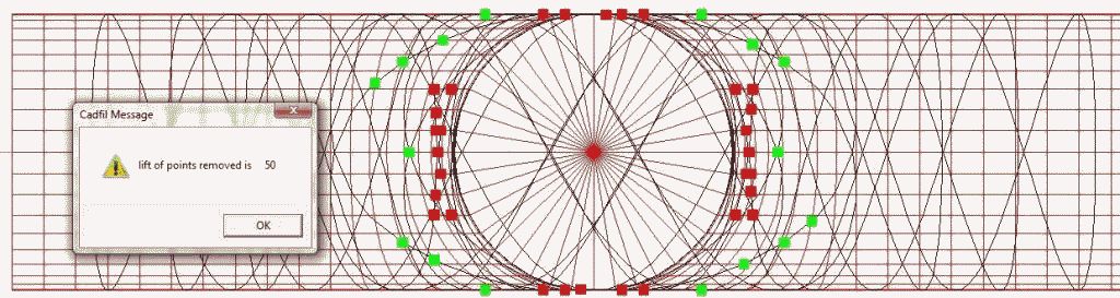
Click OK to continue. The path will be check again and some additional points may be found. Keep clicking OK. A summary can be found in the text window (see below).
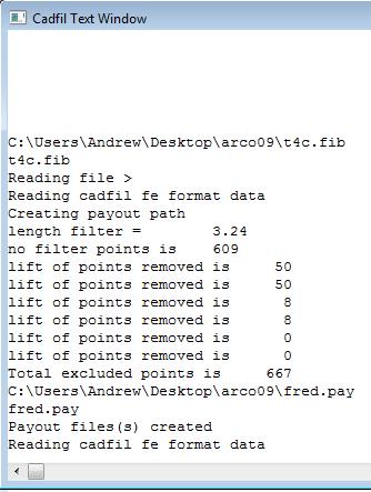
The final step is to give the payout path a file name. The default is the same name as the .FIB file but with the .PAY extenstion. The payout path is created using the mandrel clearance envelope data specified when the mandrel was generated.
The final step is to post-process the path. The 4 axis (no twist) option or the 6 axis options should be used.