Initial design of a drive shaft
In this example we consider a relatively slender carbon epoxy shaft used for power transmission. For this type of application the composite materials have a distinct advantage as the lower stiffness to weight ratio often means a centre bearing & universal joint can be eliminated leading to weight, installation and maintenance and material savings as well as a lower inertia shaft which reduces energy usage and drive train load. This software is intended as a tool for quickly establishing a design which depending on the criticality should be subject to a prototype and test program or more rigorous and detailed analysis such the FEA method. Note this example was created with Cadfil Version 7.87, stress module version 1.01
Specification
- Length: 4.5m, the ends are assumed to be 'pin' jointed
- Material: Standard Modulus, High Strength Carbon Fibre with epoxy resin
- Drive Max Torque 500Nm, Design Torque 1000Nm
- Mandrel diameter 150mm
- Maximum speed (over-speed) 1000rpm
Design Process
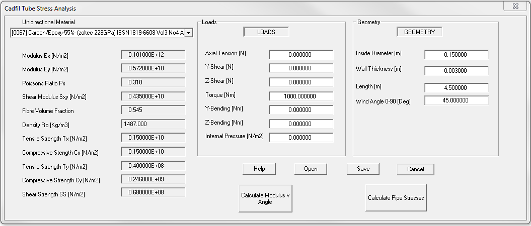
The first consideration is the torque load, for a pure torsional load the most efficient fibre angle is +/-45 degrees. A first guess design is shown in the figure below assuming 3mm wall thickness on a 150mm internal diameter with a carbon/epoxy material ( a Zoltec high strength carbon fibre at 55% volume fraction). The output is shown in the link from file d01.txt.

D01 Input data
As can be seen in the output the factors of safety (FOS) for fibre stresses are relatively high (>40), the lowest FOS are for the two torsional buckling methods at 2.3 and 4.0 so it is not feasible to make the tube wall much thinner. What can be noted is that the natural frequency Fn is 13Hz (800rpm) so this shaft will fail through excessive vibration or will damage attached parts such as bearings. To correct this we need to make the bending stiffness higher by either:
- Reducing the wind angle which will reduce torsional performance so we will need to also increase the wall thickness
- Increasing the shaft internal diameter
- Adding some low angle winding
To illustrate this we went back to the data parameters above and set the wind angle to 8 degrees and the thickness to 1.5mm (0.0015m), in the results (file d02.txt). The natural frequency of this shaft is 33.5Hz (2000rpm) which is OK, you will note that this 'low angle only shaft' has factors of safety for torsional buckling of less than 1.0. What we would like to do is combine low an 45 degree winding. Structurally we know that if d01 design has additional low angle material it will not get weaker, the section will increase and the low angle will not attract any torque load as the shear strain is controlled by the 45 degree material. What is not known is the effect the additional mass of the 45 degree winding will have on the whirling speed. We can make a quick estimate of the effect. The D01 design had a mass of 9.649Kg and the d02 design had 4.777kg. We need to add an extra 9.6 KG of distributed mass. We can do this by factoring the density in d2 by (9.649+4.777)/4.777 which is 3.02, so the density would go from 1487 to 4491Kg/m3, the results are shown in the link (file d03.txt). With the extra mass the whirling speed reduces from 2000rpm to 1140 rpm. In reality the 45 degrees increases the section properties and will thus give some increase in bending stiffness so this will give some additional safety.
From this quick analysis we can see that 3mm at +/-45 degrees and 1.5mm at +/-8 degrees appears to give a reasonable starting point for the design using 14.4Kg of material. From a practical point of view when the winding programs are developed each layer will have a certain thickness which will require some approximation of how many layers are required. It may be that some adjustment of the design thickness is made in response to this as we can only have an whole number of layers. Additionally it would be normal to intersperse the two angles as this will give a better and more resilient composite.
As a final point of note we re-ran the analysis using a thickness of 4mm and a wind angle of 25 degrees. The minimum FOS is 4.4 an the whirling speed is 1490rpm with a mass of 12.9KG. Given the materials length and diameter in this case a single angle solution might be more simpler an more efficient (file d04.txt)?
In summary there are several ways in which a suitable design can be achieved. This article serves as just an illustration of the ways in which the design can be developed.
Contact us today
If you need further information or would like to buy this software as a stand alone item or to add to an existing Cadfil package then please contact use via the link at the top of the page and we will be happy to help.
[an error occurred while processing this directive] Cadfil Help contents
 Cadfil.com Home