Tutorial 1: - Quick CAD – Vessel With End Caps
 Cadfil Help contents
  Cadfil.com Home
In this example we create a winding program for a typical gas bottle such as compressed natural gas (CNG) cylinder. The Winding consists of:
1 layer Helical +/- 15 degrees V120P03
A Transition (joining path hoop to helical) V120T02
2 layers at Hoop (circumferential winding on the cylinder) V120H01
This tutorial is not meant to represent an actual complete design, is intended to illustrate some of the methods and tools available in Cadfil-Lite+. This Tutorial was created with Cadfil 9.54, other versions may have small differences.
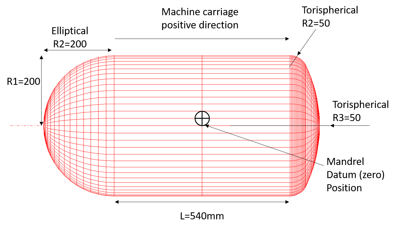
This example uses Vessel With End-caps from QuickCAD Menu. A mandrel geometry is shown below, this is a cylinder with one elliptical end cap with a specified radius (R2) and one torispherical end cap comprised of two radii (R2 and R3). For more information on parametrically defined endcap types, see the vessel with endcaps help page. A very good torispherical approximation to other shapes such as the isotensoid shape can usually be made. Conical and spherical end caps can also be used. We have not modelled end bosses on the end caps for filling points. We just need to control the size of the winding end openings to suit the actual boss condition. Before starting some planning is required as we may end up creating several files and it makes things easier to have a logical naming system. The vessel is designated V120 and the parts are V120xyy where x is H,T,P (Hoop, Transition, Polar – low angle) and yy is the position in the winding sequence i.e. 01,02,03. Obviously a user can name files in anyway they wish so long at the names are not too long and do not have prohibited characters. File names with spaces can cause problems so avoid that also.
Layer 01 – Helical winding
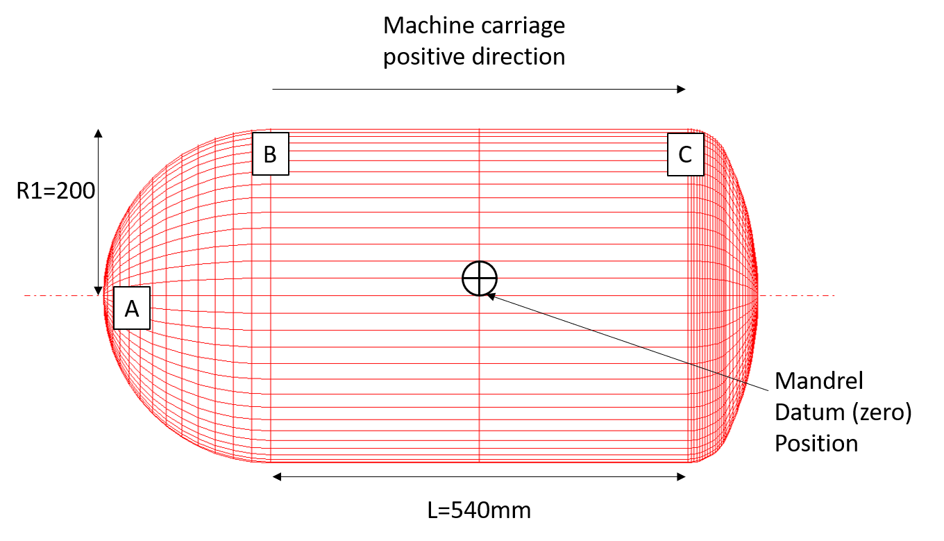
The first full layer is a low angle polar wind that will start at position A. The next full layer is a double hoop layer that will wrap from Position C to B and then back to C ( or B > C > B). In this instance the transition path is likely to be better from A to C, directly from A to B would always slip.
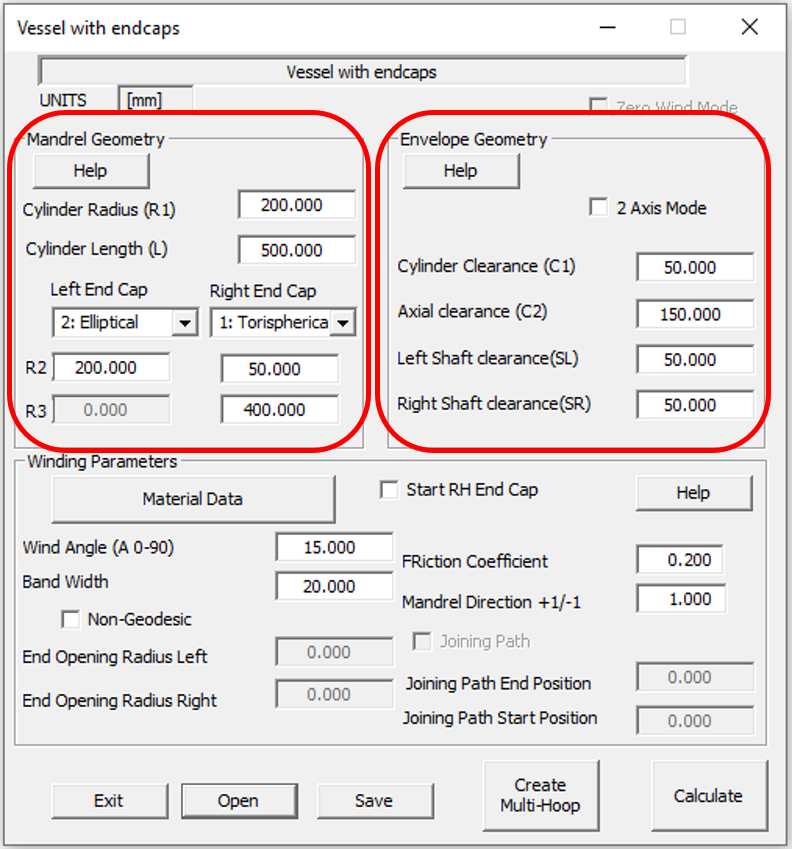
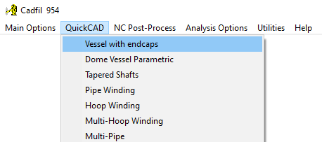
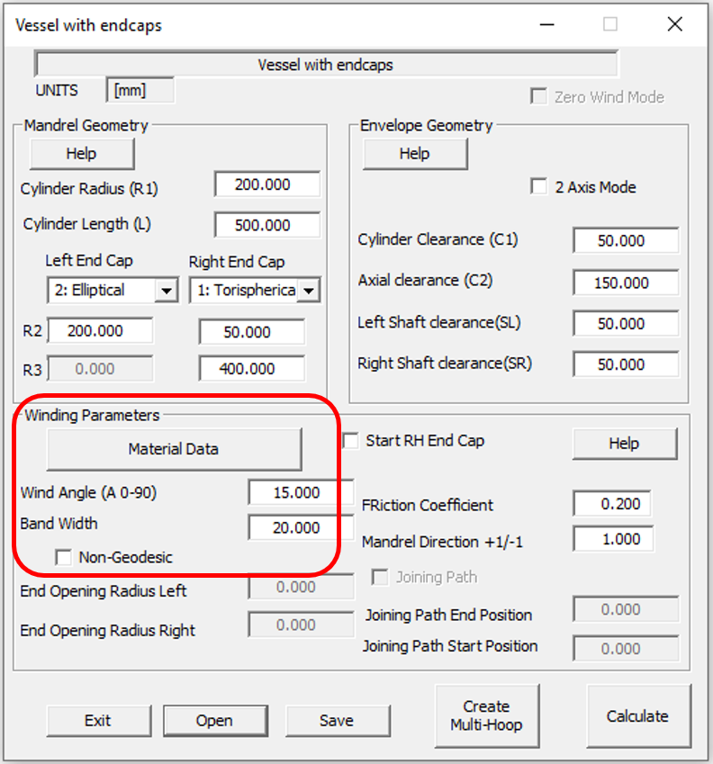
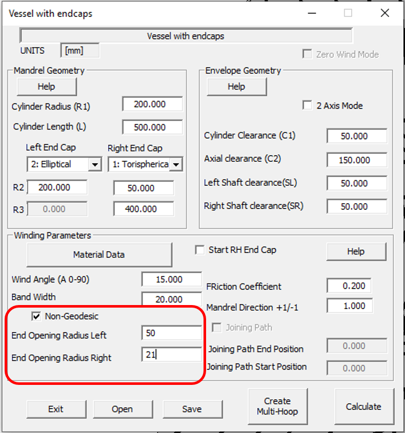
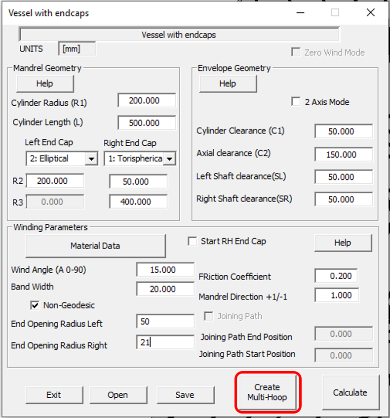
1] From The QuickCAD menu select the Vessel with endcaps option. Please note that there are different Cadfil options and packages and some of the screen shots may have menu options that are not available on your system. The Mandrel geometry for this vessel is defined by the data parameters in the left hand red circle area in the picture below. You might wish to refer back to the mandrel diagram at the start of this topic.
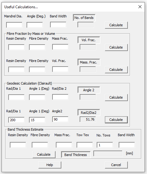
2] The designers specified a wind angle of 15 degrees on the cylinder. If we consider the geodesics path (shortest path for non-slip) the end-cap opening are radius is fixed at 200xSin(15)=51.76mm (200 being the radius of the cylinder).
3] If you do not have a calculator to hand this geodesic calculation can also be made using 'Useful Calculations' option the 'Utilities' Menu. If you enter radius 1 & angle 1 as 200 & 15 then at the turning point angle 2 =90 and thus radius 2 is given by clicking the calculate button. It must be remembered that this 'opening radius' is for the centre of the fibre band and the actual radius of the opening is reduced by half the band width.
4] The clearance parameters for the winding machine C1=50, C2=150, SL=50, SR=50, shown in the right hand red circle area below. A full description of the Machine envelope (clearance) can be found by clicking the help button.
5] For an initial trial we will have a wind angle on the cylinder of 15 degrees, band width of 20mm and will have geodesic winding (non-geodesic box is not ticked) as in the circles area below.
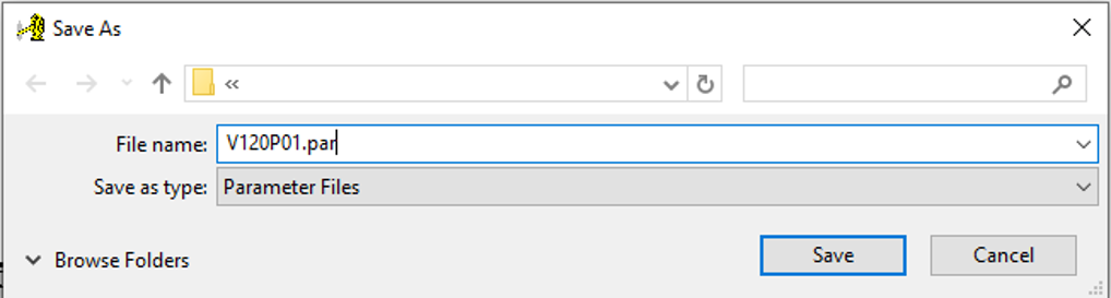
6] You will need to save these parameters before calculating the fibre path. This can be done using the save button, but once this has been done the parameters can be recalled using the Open button. Using the naming convention described at the top, this polar layer would be titled V120P01.
7] Clicking the calculate button starts the path calculation. The next step is to pick a band-pattern to complete the path generation. The band pattern dialog is shown below.
8] Band pattern is discussed at length in the help file, which can be accessed directly from the help button or in the Band Pattern Selection page. For this example click the top line, Option 2 to have a band pattern of 6 and then click 'OK'. You can the choose to save an updated mandrel
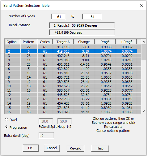
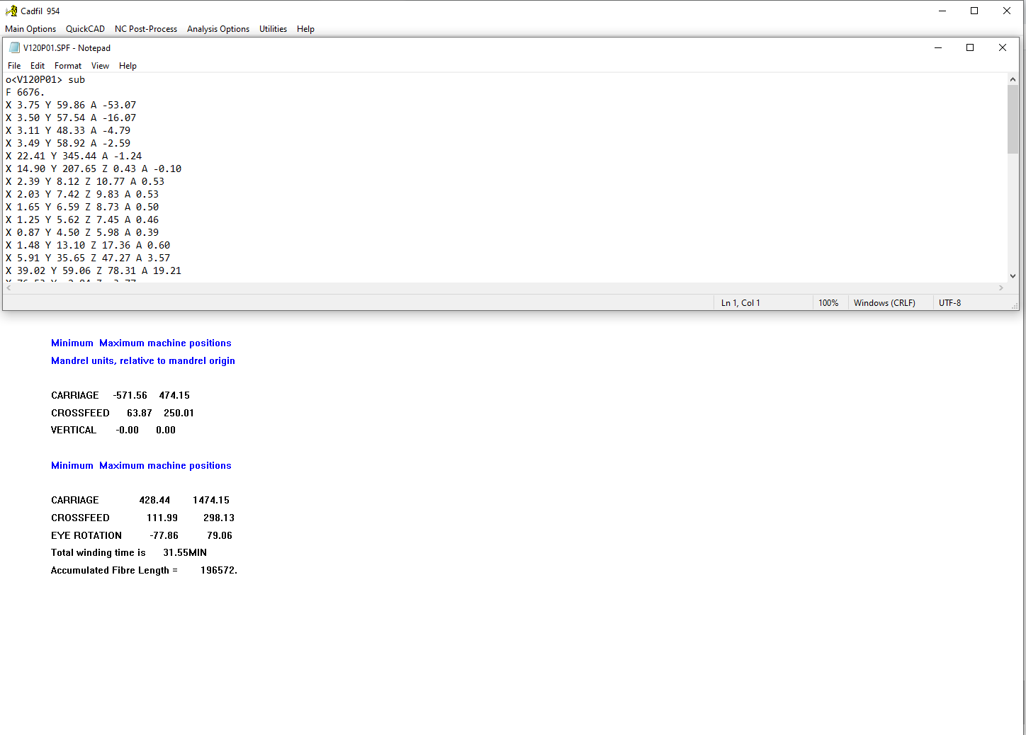
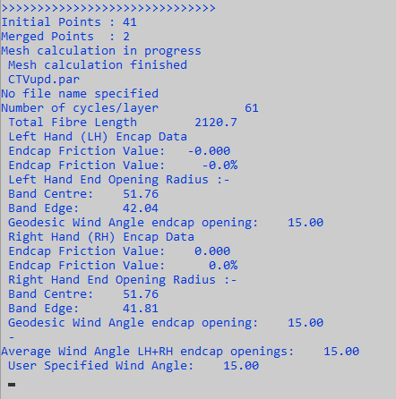
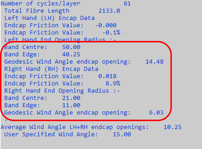
9] Looking in the text information window (below) we can see that for a 15 degree wind angle the left hand end (LH) opening has a radius of 42mm if we consider the band edge and 52mm if we consider the centre of the band. Because this is geodesic winding the band centre opening is the same at both ends and is fixed by the 15 degree wind angle.
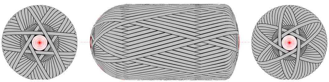
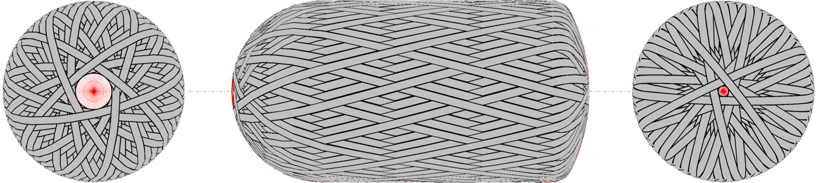
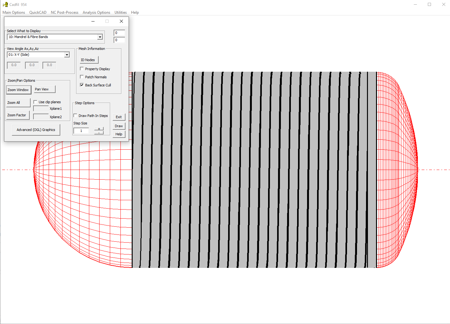
10] Using the Views option (as at steps 11-14) the winding can be viewed, as illustrated on the next picture. The Left End Opening is approximately R42 (Ø84), the Right End View Opening is approximately R42 (Ø84)and the “Band Pattern is 6”.
11] We will now remake this program with non-geodesic winding. We will assume we want to close the winding to a Ø80 (R40) at the LH end cap and Ø22 (R11) at the RH end. As we program the band centre opening radius we will thus need 50mm and 21mm at LH and RH ends, this allows an adjustment of 10mm (half a band width) for each value. Pick the 'Vessel With End-caps' option from the 'QuickCAD' Menu. Click the 'open' box and then select the file we saved earlier. Note we tick the non-geodesic box and specify the end radius values. 50mm for the LH end and 21mm for the RH end as shown below.
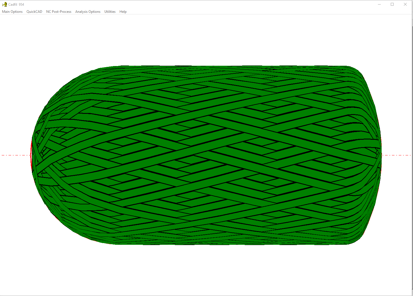
12] Click the save button to re-save the V120P03.par file with the new data. On clicking the Calculate button the path is created and we can see on the picture above that we have the new end openings values and that the path is well within the friction limits for not slipping. The winding can be seen on the next picture. The LH End View Opening is R25 (Ø50), the RH End ViewOpening is R30 (Ø60) and the band pattern is 17 (15 degree wind angle).
Layer 03 – Hoop winding
13] Referring to our winding sequence (helical layer, joining path, hoop layer), we have now made a low angle helical layer, the next step is the joining (transition) path to the double hoop layer. However it makes more sense to generate the hoop layer first so that we know what we are joining!
14] From The QuickCAD menu select the Vessel with endcaps option again. You should be able to open your previously defined mandrel that was used to create the helical layer. after this, you will need to press the 'Create Multi-Hoop' button at the bottom right hand corner of the dialog box.
15] The software will ask for the number of hoop layers required. For this example it will be 2 (C,B,C as defined in the diagram at the top)
16] The software will then ask if a step in is required from the cylinder end. If the step in is 0, half of the fibre band will be over the edge of the cylinder, therefore half a bandwidth is usually counted as a default step in.
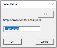
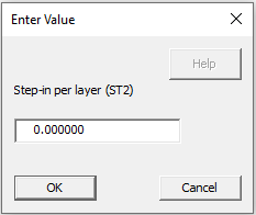
17] If you are winding a large number of hoop layers, it is possible that this would cause a sudden change in thickness between the dome and the cylinder. This can be prevented by adding a step in per hoop layer. This means each layer will start further in and be slightly shorter than the previous layer, to allow for a more gradual thickness build up.
18] Finally, you will be asked if you want to start hoop winding from the X- end (B on the diagram) or the X+ end (C on the diagram). In this example we have chosen to start from the X+ end in order to make it easier to join the paths.
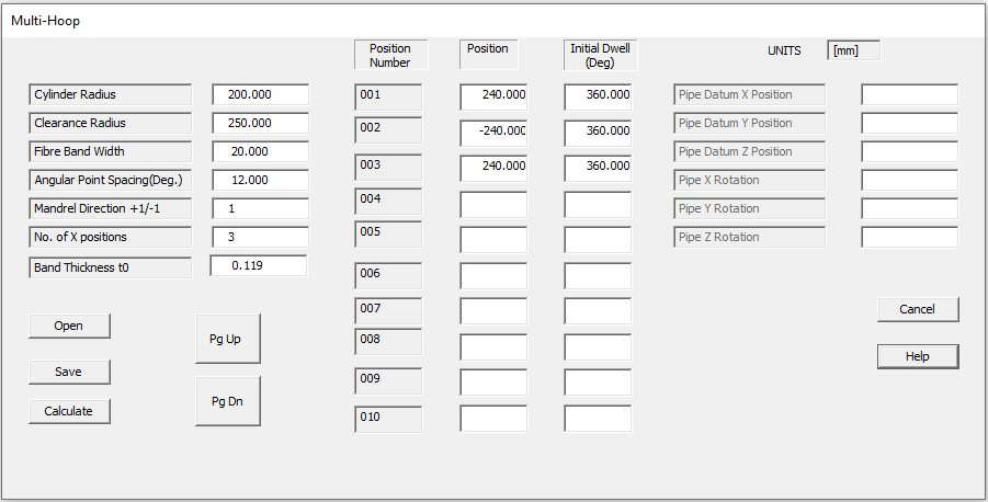
19] The Cadfil Multi-Hoop dialog box will open, with all the information already pre-populating the page as shown below. It is possible to make more adjustments here, but it is likely that no more adjustments will be required. There are 3 data points required in order to define the 2 layers. For more information about the parameters on this dialog, either press the help button or see the Multi-Hoop Winding page.
20] The last step is to press the save button to save the parameters before pressing calculate.
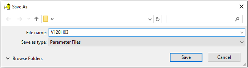
21] At the 'save as' dialog (right) enter a name for the parameter file. Enter the planned file name, V120H03.par and click the 'save' button.
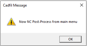
22] Click 'OK' to clear the 'NC Post-Process' message, we will do this step later.
23] At this point, you will likely have the 2D graphics window displayed. If you have the 3D graphics enabled, you can swap back by pressing the 'Change to classic viewing' button. Conversely if you are in the 2D Graphics window and want to view the 3D option. you can press the 'Advanced (OGL) Graphics' button.
24] The 2D band structure on the vessel will be displayed (see picture below).
25] Click the 'exit' button on the dialog to close it.
26] The next step is to start a combined winding. This is file that defines a sequence of programs that make a complete multi-layer program.
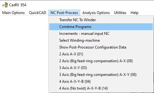
27] From the 'NC Post-Process' Menu pick the 'Combine Programs' Option. The 'Combine Programs' Dialog will pop up.
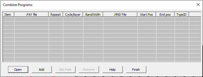
28] Normally we could pick the 'Open' option to retrieve a list that has been previously made however we are starting with a blank sheet so we pick the 'add' button. The add button opens a file browser dialog that will allow us to select payout (.PAY) files. Pick to Open the file V120H01.PAY for the hoop program.
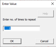
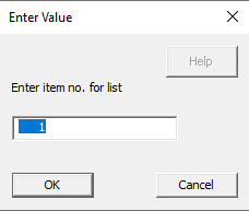
29] You will be prompted for the number of times to repeat the program, click OK for the default value of 1 (left picture below). The second prompt (right picture below) is the item no. for the list. The default will be to add at the end of the list but we can use this feature to insert a program into the list at another location. Select OK for the default which is to append the program.
30] Repeat 'ADD' for the fileV120H03.PAY for the low angle program.
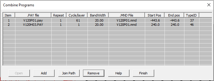
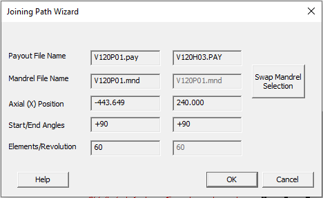
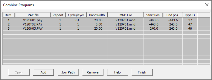
31] The dialog should now look like the picture above. Data for each for each program file is summarised here. The key information we need for the joining path is the end X position for the low angle program (x=-443.6) and the start position for the hoop program (X=240.0). Also note the mandrel file is the same for both programs (V120P01.mnd).
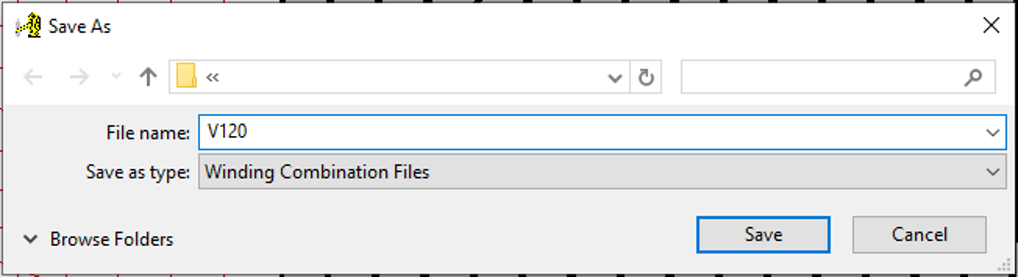
32] Click the 'Finish' button and then you will be prompted to save the combined program, save with the name V120.CTL as shown in the picture below.
Layer 02 – Joining Path
33] We now create the Joining path. From the 'NC Post-Process' Menu Pick the 'Combine Programs' option and then open your combined program (V120.CTL)
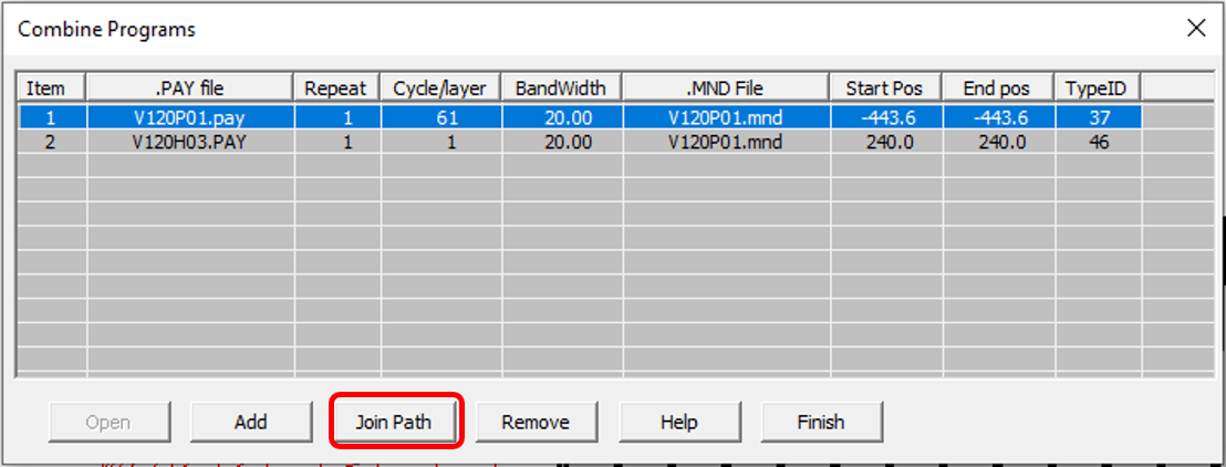
34] The joining path will be required to link from PAY file 1 to PAY file 2. Therefore click on PAY file 1 and press the 'Join Path' button to start the joining path wizard.
35] The joining path wizard will take the end X position of the first path and the start X position of the second path in order to determine where the joining path goes from and to. After checking the data is correct, press ok to continue.
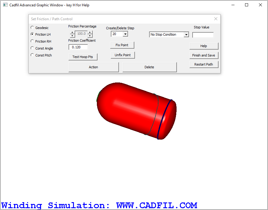
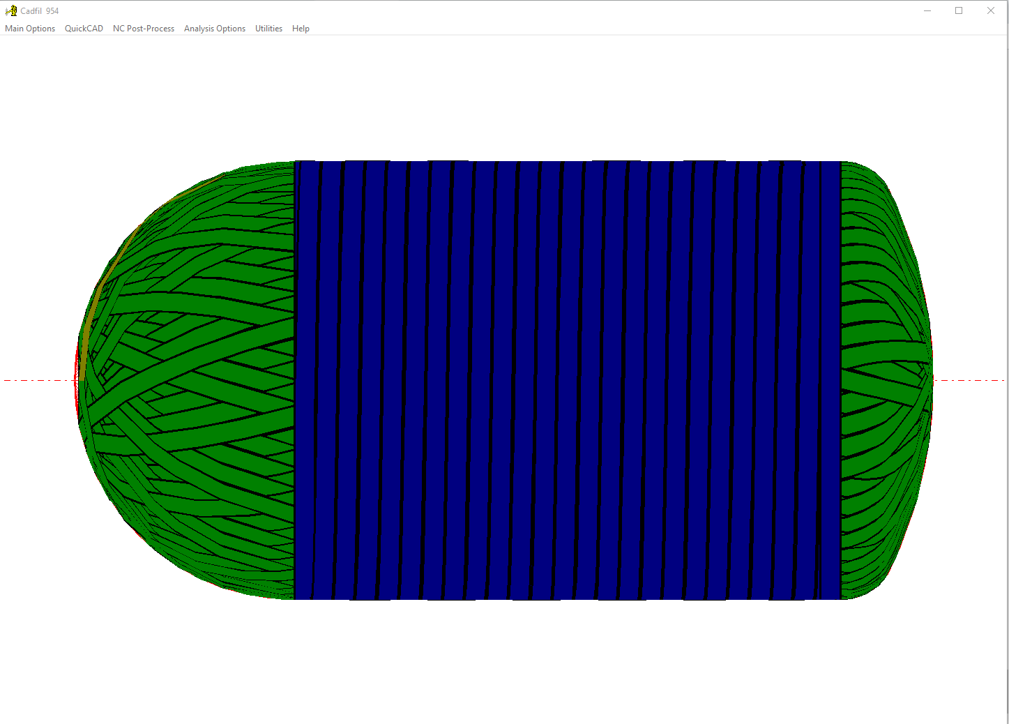
36] The 3D graphics window will open as shown below. By repeatedly pressing the 'Action' button, the fibre path is built up on the mandrel (this is the thin axial line). As the geodesic option is selected, the fibre will follow the geodesic path. It is possible to build up the fibre path quicker by changing the "Create/Delete Step" number so that more steps are added at once. The dark blue band on the mandrel is showing an X value of 240, as this is where the hoop winding path starts, and is therefore where the joining path needs to end.
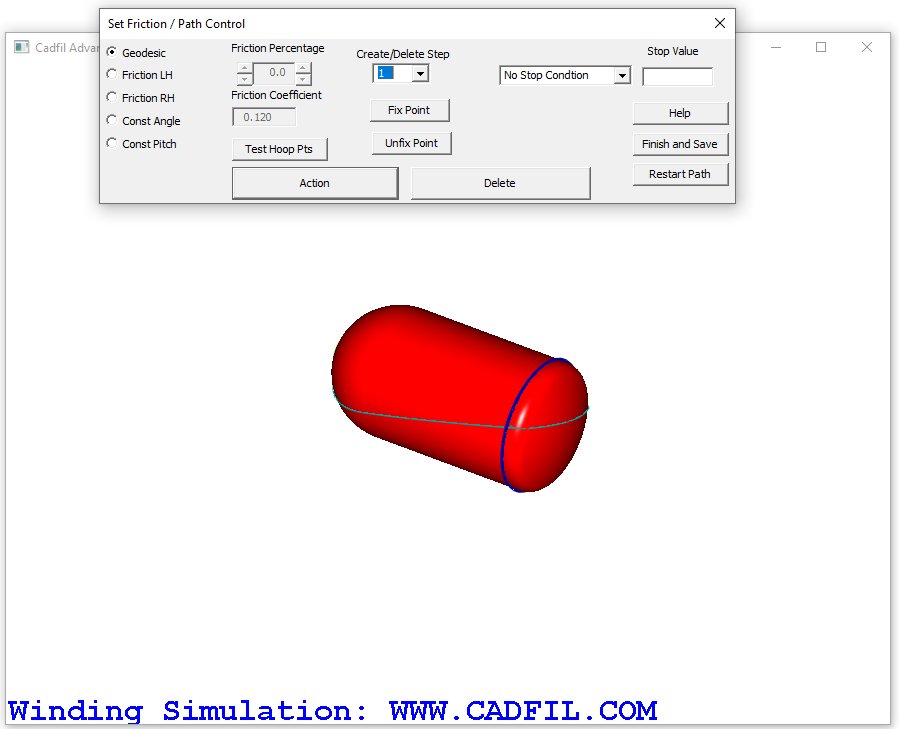
37] As we are at on a cylinder the geodesic path would just circle around the mandrel with no axial movement. We need to apply friction to deviate the wind angle and steer the path to the desired location on the RH end cap where the low angle wind starts. Before attempting to create a new path, the current path has to be removed. This is done by repeatedly clicking the Delete button, which is the reverse of the Action button.
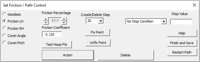
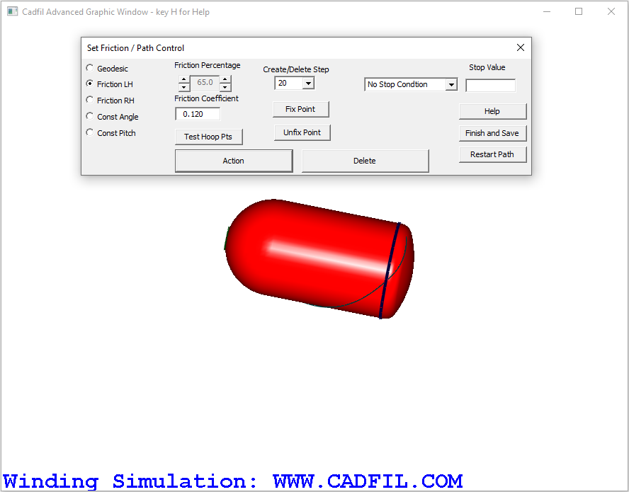
38] Friction is applied as a percentage of the maximum friction that can be applied without the fibre slipping. In the example below, the left hand friction box is checked, and the friction has been set to 65% of the maximum friction value. To test the effect of this, the Action button is used as before to show the fibre path.
39] As shown on the picture below, the additional friction has bought the turning point or 'hoop point' closer to the dark blue band. More friction is still required to bring the hoop point to an X value of 240.
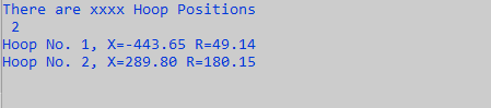
40] The 'Test Hoop Pts' option can be used to check the exact turning point. In the picture below the results from the text window can be seen. Currently the hoop point is at an X value of 289.80, so more friction is needed to give an X value of 240. Once again, before attempting to create a new path, the current path has to be removed using the Delete button.
41] If 100% of maximum friction is used, it gives a drawing as shown below. The hoop point is clearly before the dark blue band, so this means that there is too much friction applied.
Testing the hoop points shows that the hoop point has an X value of 171.70. Therefore the % friction required for an X value of 240 is clearly somewhere between 65% and 100%.

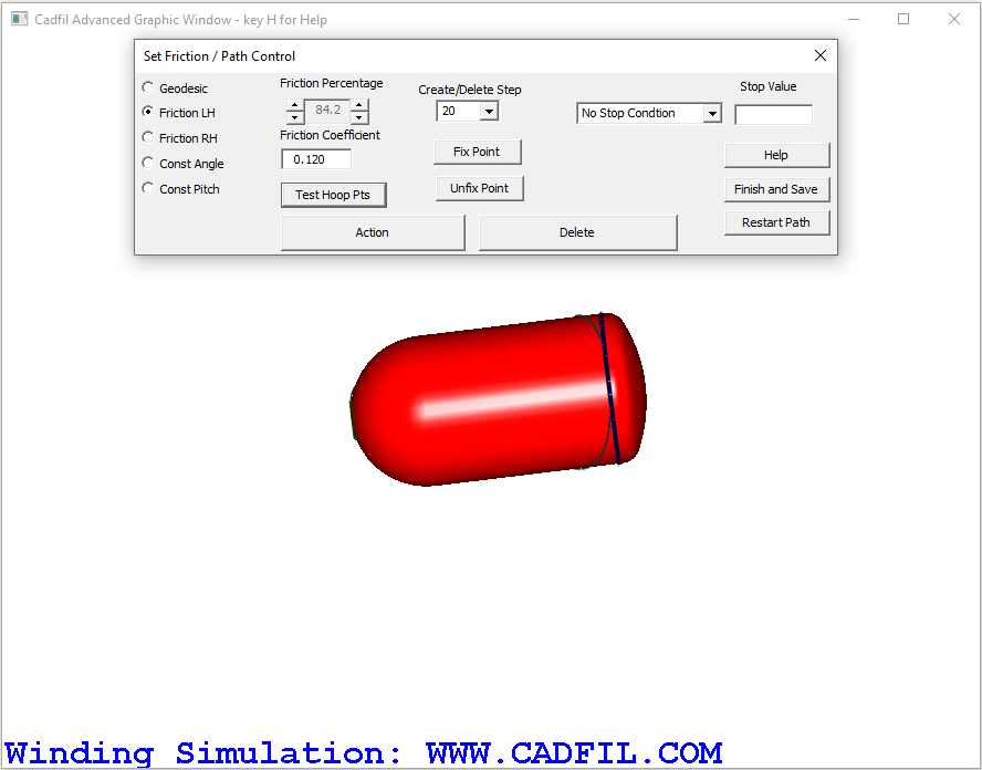
42] Through some experimentation to find the friction value that gives the closest result for X value, it becomes clear that the best friction value in this case is 84.2%. As shown on the pictures below this gives a final x value of 240.03.

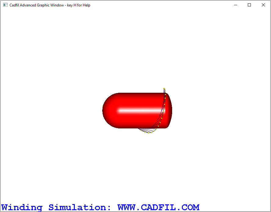
43] From the Menu pick the 'Finish and Save' Option and save the path as V120T02.fib and then Click 'Yes' to create the payout path, and save as V120T02.pay. You will be given the option to create a reverse payout path, which would be useful if you intend to go from a hoop wound layer to another helical layer with the same winding angle as the first helical layer
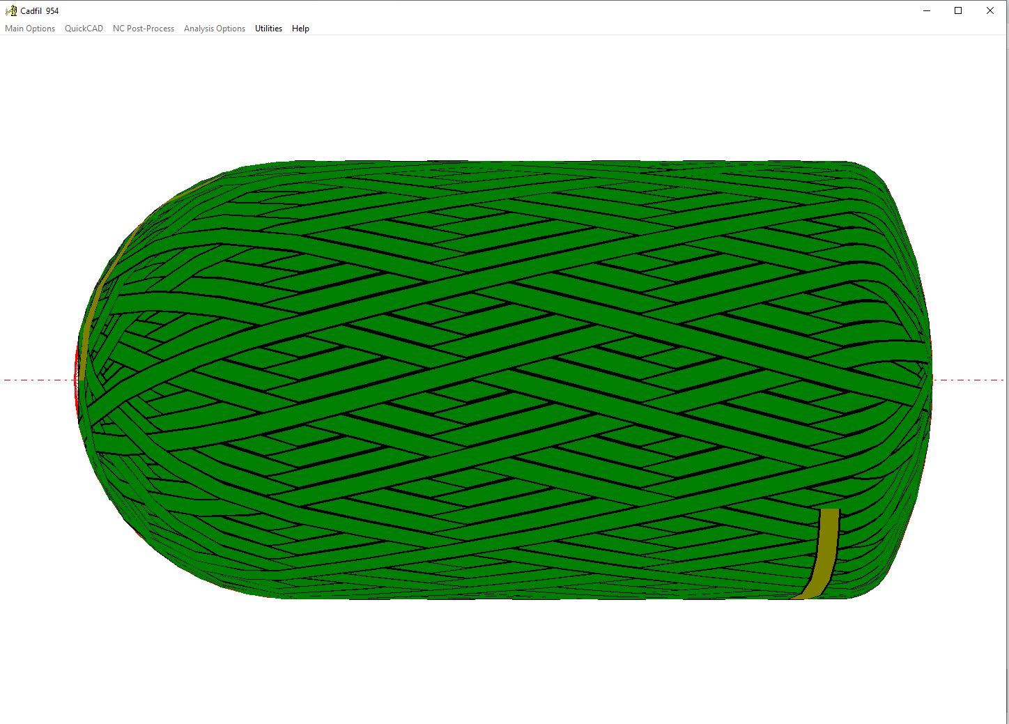
44] The advanced graphics window will now show the joining payout path, where you can see the transition from the axial path to preparing to wind a hoop layer.
45] The last step is to close the advanced graphics window and open the 'Combine Programs' Option from the NC Post-Process menu again.
46] Click the open button and open the V120.CTL file we created earlier.
47] We then 'add' the transition file V120T02.pay at position 2. The display should then look as the picture below.
48] Finally click 'finish' and save the combined file V120.ctl.
49] The winding program is now complete. If you would like to see the complete winding program, you can open the 'View Multiple Pay Paths' Option from the Main Options menu
50] The last step will be to Pick 4 axis post-process from the NC-Post Process menu and pick the V120.CTL file to post-process with V120.prg as the output NC file. There are a number of post-processor configuration specific options which are described in the help file, or also online in the post-processing section of the Cadfil website help page. Finally we have the completed NC data for winding the CNG tank.