
Vessel With Endcaps
 Cadfil Help contents
  Cadfil.com Home
An example can be found by following the link.
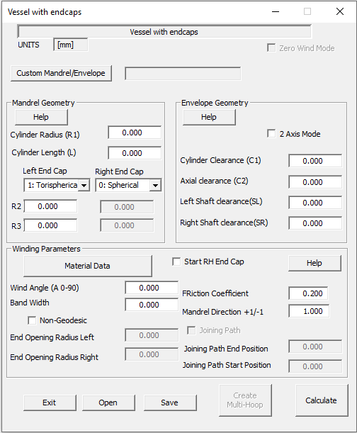
Different end-caps can be specified for each end of the mandrel from the pull down list box, the end caps have parameters R1, R2 & R3. The dialog and End-cap types are shown below
Custom Mandrel/Envelope
From Cadfil version 9.71, it is now possible to import a vessel with endcaps geometry from the Cadfil Axsym Mandrel editor.
For a mandrel to be imported it must meet the following criteria. It must be a cylinder of constant radius with an endcap (or dome) at either end. The dome must close to a radius of 0. A half mandrel with the symmetry option can be used
Mandrel Geometry
For the conical end cap (not shown above) the R2 parameter is the axial length to the apex of the cone. The clearance parameters are explained in the following diagram. Please note that having C2 > half the with of the payout head is advisable to avoid collision with the end-cap.

The user also needs to specify the fibre band-width (W) and Winding angle(A).
For unequal end openings the non-geodesic box can be ticked and then the openings at each end can be specified. Please note that these are for the centre line of the band so an end opening radius 0.5*W larger than required should be used. There are some known issues/problems with the non-geodesic winding on this option.

Hoop Winding
After vessel data has been successfully entered, saved and calculated it is possible to quick launch a hoop winding program using the Multi-Hoop Button. This basically creates a Multi-hoop parametric job taking data such as the cylinder end positions, mandrel radius, mandrel clearance and band-width and then populates a multi-hoop dialog. There are some questions that are asked in the process. The number of layers, a layer being a single traverse of the cylinder, the Step-in from cylinder ends (ST1), whether to Start at Left (X minus) end? and the Step-in per layer (ST2)'. The Step in ST1 can be seen in the following figure. This allows the user to shorten the winding from the cylinder end. Sometimes if you wind too close to the ends some strands of fibre may fall over the edge. With multi-hoop the band centre position is programmed so the default value presented for ST1 is half the band-width. If there is more than one later specified each subsequent layer can be reduced by a length ST2 as can be seen in a following figure. This allows the edge of the hoop layers to be feathered so that the is not a sudden step in thickness that may causes a stress-raiser and it also can give a neater looking edge to the winding.


Zero Wind mode
This is a developmental option that is not matured for user release
The zero Wind tick box is a special option for zero degree winding through pins at the cylinders ends and is described elsewhere.
The process is:
1] Enter the data parameters
2] save the parameters and give them a file name (<name>.par)
3] Calculate the program with the 'Calculate button'
4] Exit the dialog and review the payout data in the payout viewing option that is automatically run. The payout
5] Review the messages in the Cadfil text window, this shows errors and other important information.
6] Exit payout viewing and post-process the <name>.pay file.