Tutorial 3: - Quick CAD – Tapered pole with pin ring
 Cadfil Help contents
  Cadfil.com Home
In this example we create a winding program for a tapered pole using a low wind angle. To prevent excessively long turning areas where material would be wasted, we use pin rings to allow the fibre to change direction quickly without slipping.
This tutorial is not meant to represent a complete design, it is intended to illustrate some of the methods and tools available in Cadfil. This example was created with Cadfil 9.59, other versions may have some differences.
This tutorial also is designed for a 3 axis machine, with a constant clearance to the mandrel along the taper.
We use the Tapered Shafts option from the QuickCAD Menu. The geometry required for the finished pole is shown below, The pole required will have a length of 5m, and will taper from a width of 500mm to a width of 400mm.
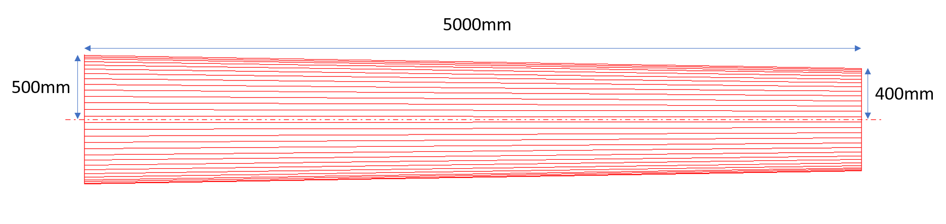
It is important to note that we will need to program a winding length of more than 5m, to allow for a length of turning at either end of the mandrel where the fibre changes direction. An estimated winding length of 5.5m will be used to begin with, with the understanding that the turning zones, including the pin rings will be cut from the final part, leaving the 5m tapered pole. This means that the turning length calculated my Cadfil must be less than 250mm at both ends in order to ensure that the angle is constant within the 5m pole.
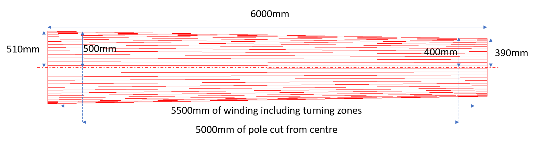
In order to avoid winding to the very edge of the mandrel, a 6m mandrel will also be used. This means that we will need to calculate a new geometric set for the mandrel. The gradient of the radius of the pole is (100/5000) or 0.02. Therefore if there is 0.5m of mandrel added to either end of the finished pole, the mandrel must have a start radius of 510 and a end radius of 390 to give a pole of start radius 500 and end radius 400. The diagram below shows the new dimensions, although this is illustrative and not to scale.
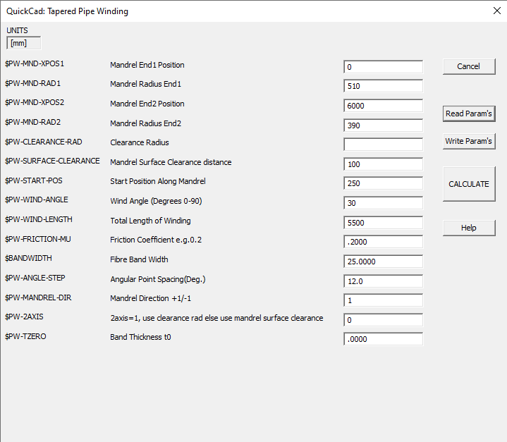
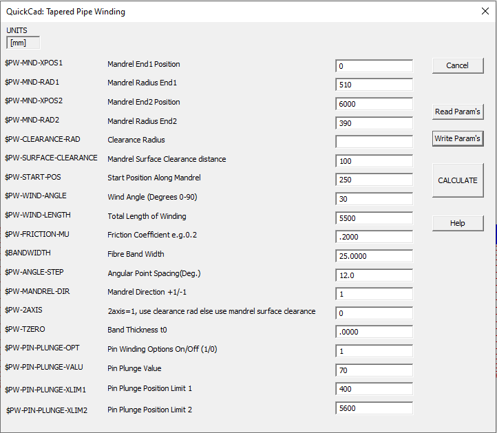
We now have data ready to enter into the Cadfil dialog box shown below. As in the picture above the mandrel is 6m, so the mandrel end points are set to 0mm and 6000mm with the calculated start and end radii of 510mm and 390mm. The clearance of the payout eye to the mandrel has to be relatively low in order to ensure that the fibres engage better with the pin ring, however not too low as to risk collision between the payout eye and the pin ring. For this example I have set 100mm clearance (note that the 2 axis option $PW-2AXIS is set to 0. This is very important when pin rings are used, as otherwise the payout eye will not move inwards in the y direction towards the mandrel as the radius decreases. This means that it is more difficult for the fibres to engage with the pin ring).
The winding start position has been set as 250, so as to leave 250mm either end of the mandrel where no winding takes place. The band width and winding angle are also selected here. This leaves the friction as the last key parameter to set. The friction would normally be a low number (e.g 0.1), due to the tendency of fibres to slip while turning. This would give a very long turning distance for low angles, and as stated above, the turning length in this project must be less than 250mm. This is the purpose of the pin ring, the friction value can be set higher as the pins will prevent the fibre from slipping, and setting the friction value higher will in turn reduce the turning distance. If the friction value is set very high, however, there is a risk of very sudden and jerking machine movements as the machine attempts to turn near instantly with no turn length, therefore some testing of friction values is required in order to give an appropriate turn length. For this example a friction value of 3 is used to begin with.
When all parameters have been set, the file can be saved. The calculate button is then pressed in order to continue to selecting a winding pattern
When selecting a winding pattern, for cases with a pin ring, it is useful to have some dwell, this is where the fibre winds at a 90 degree angle for a short time during the turning zone, so that the x- path starts from a increasingly different place to the the endpoint of the x+ path. Examples of varying amounts of dwell are shown below.


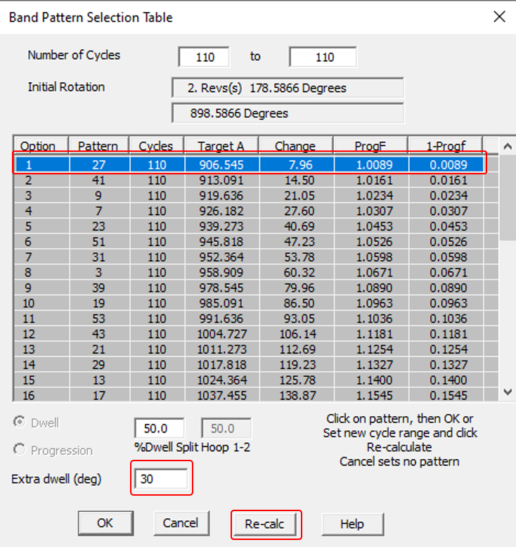
For this example a pattern with a 30 degree dwell is used. Therefore 30 is typed into the box labelled "Extra dwell (deg)" and the "Re-Calc" button is pressed to give winding patterns with this amount of dwell. A winding pattern can then be chosen. Note that the "change" value in the pattern table is the amount of total dwell rotation at the two ends needed to make the pattern work. If you want a minimum amount of dwell the extra dwell and recalculates builds the extra dwell into the winding. You still get some addition dwell from the new change values in the pattern that you pick.
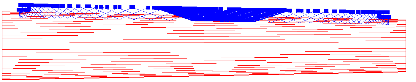
Cadfil will then show the winding path on the mandrel.
At the same time, in the text window, Cadfil will display information on the turn length at either end, the total turn length, and therefore the length of winding that is at 30 degrees (the useful pole).
In this case the turn length at either end is 171.064 on the x- end, and 133.802 on the x+ end. Both of these are within the 250mm maximum turning zone that was specified at the start. If this value for turning length was either very short, causing sudden machine movements, or too long, so that there would be sections of the pole that are not at 30 degrees, then it would be worth reconsidering the set friction value.
If the x- end is considered, 250mm has been allowed for as "waste zone" which will be cut off from the final pole. Within this 250mm however, 171mm is turning zone, and the remaining 79mm is winding that is at 30 degrees. Within this 30 degree waste section is the ideal place for the pin ring to sit. If this 79mm length is unsuitable for the pin ring to sit in, then either the friction value would have to be re-considered, in order to change the turning zone, or the 250mm that was allowed for waste zone could be changed (for example 300mm waste zone could be allowed, where the winding takes place from a start position of 200 instead of 250, and the total length of winding is 5600, not 5500). A full drawing of the dimensions described is given below.
From Cadfil 9.59 onwards, 'pin plunge options' have been added for tapered poles. These options cause the payout head to move inwards towards the mandrel in the areas outside the pin rings. When the payout head plunges towards the mandrel (with lower clearance), this causes the fibre to engage better with the pins.
In order to use the pin plunge options, they must first be activated in the post-processor configuration data (SM file). Within the configuration data, the variable $PW-PIN-PLUNGE-ASK must be set to 1

Once $PW-PIN-PLUNGE-ASK is active, opening the tapered shafts QuickCAD will give the option to activate pin winding options.
Based on the possible pin ring area shown on the diagram above, I have chosen to have the pin rings at positions x=475 and x=5,525. I need to ensure that the payout head does not hit the pins, so I will choose the pin plunge positions to be outside the range of x=400 and x=5600. These parameters can be put into the dialog box. At the moment, the clearance is set constantly to 100mm. If I set a plunge value of 70, the clearance will drop to 30mm in the pin plunge area.
The area where the clearance value drops from 100mm to 30mm can be seen in the payout points on the mandrel drawing.
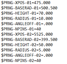
Finally the pins can be modelled in the advanced graphics option if required. The pin ring modelling page gives much more detail on how to do this, but the options used in this case are shown below:
The pin ring model can then be used within the 3D animation to see the pin plung work, as well as to check for the possibility of collisions between the pins and the payout head (if the payout head model is accurate). The following 5 pictures show stages of the animation.


Once an acceptable winding path has been created, the payout path can be post-processed in order to give the machine output required for winding.