Pin Plunge in Cadfil Pipewinder
 Cadfil Help contents
  Cadfil.com Home
Note these features are relevant to Cadfil Version 9.57 onwards
Introduction - What is pin plunge?
When a pipe is wound, the machine will wind the fibre from one end to the other, before the fibre turns around and returns to the original end, this would be a circuit. The winding is usually done at a specific angle, to give the desired material properties of the end product, but in the area where the fibre turns, this angle gradually changes to hoop (90 degrees) before inverting for the return pass. The turning area at either end, where the fibre is not at the specific angle chosen, is frequently removed, as it does not have the material properties that are required.

If the winding is at a high angle, or close to hoop, the turning length is quite short, so there is not much waste. However at low angles, the fibre can take a long time to turn by friction alone. This means that there may be a large amount of waste. Trying to use a short turn length in this case is impossible, as the fibre will simply slip across the surface of the mandrel. In this case a pin ring may be necessary. A pin ring is a circle of pins that sit around the circumference of the mandrel at the start of the turn length. As the fibre passes over, the pins pierce the fibre band, holding them in place and fixing the position. This means that the turn length can be short from this point. The fibres will still slip, but will rest against the pin ring. The fibres at the specified angle inside the pin ring position will not slip.
The pin plunge parameters are a set of variables that can assist with this process. The user can set x positions where the payout head will keep a higher clearance value, to avoid colliding with the pins. However when the payout head has passed the pin ring, it will then 'plunge' inwards towards the mandrel. This means that the fibres will definitely engage with the pins at the required location. The path will continue until it reaches the hoop point, where the fibres are at 90 degrees. When pin ring winding, it is normal to use a larger amount of dwell, so there is more winding at the 90 degree angle before turning back. However when the fibre begins the return pass, the payout head will move out to the original clearance, ensuring no collisions with the pins on the return pass.
Activating the pin plunge parameters
The pin plunge parameters can be activated in the post-processor configuration data (SM file). Within the configuration data, the variable $PW-PIN-PLUNGE-ASK must be set to 1

Once this is done, opening the pipewinder QuickCAD will create a dialog box, asking if the user wants to activate pin plunge options

If the pin plunge options are activated, additional parameters are available in the pipe winding QuickCAD.


Using the pin plunge parameters
$PW-PIN-PLUNGE-OPT activates the rest of the parameters, it must be set to 1.
$PW-PIN-PLUNGE-VALU gives the amount (distance) that the payout head plunges by. This value must be less than the clearance to the mandrel to avoid collision, but should be high enough to ensure that the fibre engages with the pins.
$PW-PIN-PLUNGE-XLIM1/2 gives the x values that the pin plunge occurs at. XLIM1 gives the plunge value at the x- end, XLIM2 gives the plunge value at the x- end. The x values chosen need to be sufficiently far from the pin ring to ensure that the payout head does not collide with the pins when it plunges. The payout head will also turn after plunging to get to the hoop point at 90 degrees, so the width of the payout head must also be considered.
The picture blow shows the 2D positions of the payout head. at either end the points plunge inwards, continue to the end of the mandrel, then lift off the mandrel again for the return path.

This can also be represented in the 3D graphics window. It is clear when looking at the difference between the fibre path (on the mandrel surface) and the payout path showing the position of the payout head. At the plunge location, the paths become much closer together.


Dwell winding in pin plunge
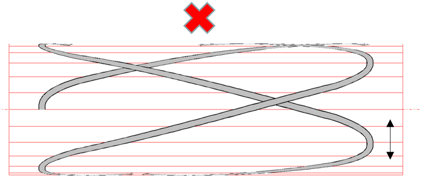
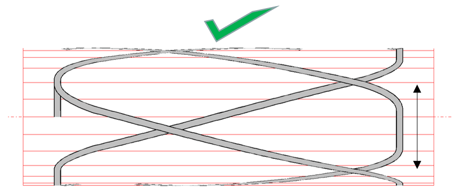
When winding low angles using a pin ring, it is important to wind with some amount of dwell at either end. This helps the fibres to engage with the pins, and also helps to remove some of the slack formed by the fibre slipping in the shortened turning area.
Extra dwell can be specified by typing a number into the ‘Extra Dwell (deg)’ box in the band pattern selection dialog, and pressing ‘Re-calc’ to recalculate band patterns with this additional dwell. The pictures below show the result of adding additional dwell.
Modelling the pins in the 3D graphics window
It is possible to model pin rings in the 3D graphics window, as shown in the picture below. For more information, see the pin ring model page.


In the 3D graphics window, the pin ring models are mainly used for illustrative purposes. However if the payout head model has been correctly defined in order to replicate the shape and size of the actual payout head, this 3D model animation can be useful to see the risk of collision between the payout head, and the pins, either when the payout head is passing over the pins, or when the payout head is plunging and turning.