Winding Trajectories
 Cadfil Help contents
  Cadfil.com Home
The geometry of the component, previously defined in mandrel generation, determines the stable paths that the user will be able to achieve. The main requirement of the fibre path, when determining its trajectory, is that it should not slip. This is accomplished within CADFIL in two ways.
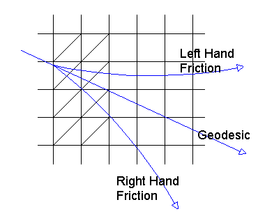
In the first method, the fibre path follows a geodesic path, this being the shortest distance between two points on the mandrel. The limitation of this method of fibre path generation is however, that once the initial conditions of start position and start angle have been input, the rest of the path is uniquely defined by the geometry of the component. Therefore, the scope for attaining an optimum winding pattern for mechanical and environmental requirements can be limited. The second method of path generation makes use of the frictional effects between fibre, resin and mandrel surface, to allow the fibre to be deviated away from the geodesic non-slip path, to a friction sustained non-slip path.

Friction Direction looking on to mandrel surface
The amount of deviation from the geodesic path is dependent upon the friction coefficient, this being dependent upon the mandrel finish, fibre and resin type, etc., and also upon the geometry of the component. A higher local curvature will increase the normal reaction to the component surface, this in turn increases the frictional forces available to sustain the fibre on the required path, and hence the fibre path will deviate faster.
The CADFIL system can make use of both of these methods whilst a fibre path is being generated, the operator deciding upon the amount of friction to be applied, and when to use it.
An example of a situation where a specific wind angle is required is discussed below.

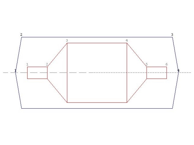
Consider the a cylinder above with domed or cone ends (or some other shape of reducing diameter). The user wishes to generate +/-30 degree winding on the cylinder but is not concerned about the end opening diameters at the cone end. Referring to the previous section on starting the fibre path the user can use the By Mouse click option to approximately fix the path start location on the cylindrical section of the mandrel near the cone end. The start angle can then be specified using the ANGLE option. In this case, as we wish to pass over the cone end first we specify and angle of 150o, (180-30=150, refer to figure). The fibre can then be advanced one segment at a time menu using the ACTION option. Setting STEP to a larger number (5 or 10 for example) will speed things up.
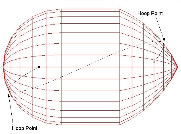
As the fibre advances down the cone the winding angle displayed will be seen to change and eventually the fibre will turn around. Thus the first hoop point has been fixed. This position will later be the start or tie on position on the winding machine! The fibre angle will then increase and then due to geodesic theory when the path is back on the cylinder the wind angle will be 30 degrees. There may be a small angle change e.g. 0.1 degrees, due to the fact that numerical methods are used. Larger changes may be seen if the mandrel is poorly defined (very few sections and/or few elements per revolution - see the sections on mandrel meshing).
The fibre will now advance (with ACTION) along the cylindrical section of the mandrel and will turn around on the dome end. Once the fibre has turned around the second hoop point has been defined and the path is complete. The fibre should always be advanced at least three segments past the point where it is seen to turn, as this allows the software to accurately locate the turning point at a later stage. If this is not done an error will be given during payout path generation. The path can now be saved and the user can exit and proceed to the payout path generation.
Specific diameter opening required
This section enables the user to generate a fibre path to give a component, which will have a specific diameter opening in one end. At an end of a component, the fibre turns round, and therefore, the fibre will be travelling in a hoop direction around the mandrel. We can therefore use this property to start the fibre at this position in the hoop direction.
The user can fix the X position by using the RADIUS option at menu 3.4. The user is prompted for the mandrel radius at the end opening, the software the start at the left and of the mandrel putting a marker on the mandrel when the mandrel radius matches the value entered. A menu with SELECT THIS POINT YES/NO? appears. If NO is selected the next location on the mandrel is shown. This option cannot be used to start on a cylindrical section at there are an infinite number of locations! If the user does not select any of the choices (or if no choices exist) the software returns to the previous menu.
Having specified the start location select HOOP U or HOOP D. The selection will fix the direction of mandrel rotation. For example, if the machine's positive direction of mandrel rotation was clockwise when viewed in a positive direction along the mandrel's axis of revolution, then the user would select HOOP U, in order that the instructions to the machine controller are not all negative. In some cases (when using the 5 axis 3 plane or the 6 axis post processors, the mandrel rotation direction can be important if the machine 'head' is not symmetric as these post processors use three Cartesian axes of motion (XYZ).
Having specified the fibre path start position the path can be generated as normal with or without the use of friction. If the path is generated fully geodesically, the end opening diameter will be the same at the other end of the mandrel (to within the accuracy of the numerical predictions). If a larger or smaller opening at the other end is required friction must be used. The path can be advanced and deleted over the mandrel end using different amounts of friction until the specific diameter is achieved. This can usually be done in 2 or 3 iterations and is made substantially easier if a mandrel end view is selected from the VIEWS menu.
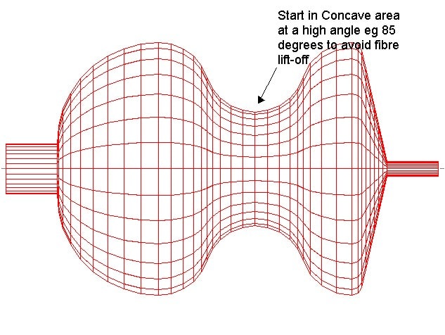
With certain mandrels it may prove difficult to achieve the desired fibre path. Mandrels having concave sections can cause problems as it may be found that the fibre turns around in the concave section of the component. In the example shown below, in order to avoid difficulties due to turn around or lift-off within this section, it is recommended that the user start the fibre at the minimum radius within this section, and travelling in a near hoop direction.

The path is developed around the mandrel until the two hoop points have been generated (as shown below), completing the path requirement for CADFIL. Alternatively, the user can start the fibre as mentioned in the previous two sections, and the user can 'steer' the fibre through the section in question, by using the friction facility of the software.
