Cadfil Elbow Winding parametric
 Cadfil Help contents
  Cadfil.com Home
Please note that the Multi-Bend Ducts (MDB) option is more flexble and can do anything this is option can, and more.
This generates full coverage winding programs for elbow (pipe bend) components. The part geometry is shown below. The elbow parametric can be invoked (if supplied) from the Cadfil parametric menu described elsewhere in this manual. The user enters a series of data parameters which are saved as a <filename>.PAR text file and example file EL1.PAR is supplied with the software in the EXAMPLES directory. The program automatically creates a <filename>.MND and <filename>.PAY when run. These can then be viewed using the payout options or post processed using the CADFIL post-process options.
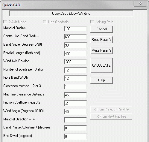
The basic data parameters are as follows :
****Elbow Parametric****
Mandrel radius (R)- The external radius of the pipe.
Centre Line bend Radius (Rc)
Bend angle (degrees) (A)- Elbows are commonly 45, 60 & 90 degrees.
Parallel length (both ends) (L)- The actual length of the cylinder on the mandrel can be longer, this is the length that will actually be covered by the winding program.
Wind axis offset distance (Yoff) - Note the direction of the Y axis in the diagram. Winding axis offset is normally thus a negative value!
Points per rotation (N)- This determine the amount of points in the final program a value of 12 to 16 is normally good.
Band width (Bw)
Clearance method 1,2,or 3) - This takes values of 1, 2 or 3 and for each value the following Clearance value has a difference meaning. For mode 1 which is the standard option this clearance value is the distance between the mandrel and the payout eye, often referred too as the free fibre length. Mode 2 has the payout points on a cylinder centred on the winding axis, the clearance parameter is the radius of the cylinder. In this mode there will be no radial (cross-feed) motion during the winding so in effect it is more like 2 axis winding. The penalty for this is that the motions of the main carriage axis will be much greater and it may be difficult to keep tension in the fibres. The range of geometry and wind angle thus may be more limited. Mode 3 has a spherical surface and is only to but used with a special cylindrical axis winding machine. For this mode the SM file values of $T11-CENTRE-AX4-COORD= and $T11-CENTRE-AX55-COORD= must be set to define the spherical centre which is the rotation axis if of the rotary machine carriage axis.
Machine clearance distance (Fl) - A mandrel clearance distance whose meaning depends on the value of the clearance method discussed above.
Friction coefficient (Mu) - used to turn the fibre in the cylindrical (parallel pipe) turning area at the ends.
Wind angle - degrees (Alpha)
Band Phase Adjustment Angle In Degrees (Phi) - If you made an elbow winding for a specific wind angle (say 55 degrees) and then wanted to wind a second layer then it would wind exactly on top of the first layer with the bands being placed directly on top of the bands from the earlier layer. Like building a wall from bricks it is better to stagger the joints so the edges of the bands are not on top of each other. If the first layer has 12 circuits to make a layer then each band occupies 360/12=30 degrees of angle, so if a band shift of 30/2=15 degrees will give maximum band stagger. Note that the initial starting position of the elbow in the machine is with the bend of the elbow in a horizontal plane and with the outer curve of the bend closest to the payout eye.
Note that care selection the winding axis offset and free fibre length is required as this otherwise can result in the elbow rotating forward and backwards in the winding machine rather than is a constant direction.