 Cadfil Help contents
  Cadfil.com Home
Overview
Poles and masts are an increasingly common application for filament Winding whether they be for lighting, communications , CCTV cameras or other applications of this type. Composite Poles have significant advantages over conventional materials and can have much better full-life cost when installation and maintenance costs are properly considered. For most masts and utility poles one of the key considerations is the bend stiffness under prescribed loads. Design standards such as BS EN40 or AASHTO-LTS5 prescribe maximum deflections under load expressed as a fraction of the pole height. The calculation of deflection is relatively simple for pole of uniform diameter and thickness as simple beam formula can be applied and hand-calculations or spread sheet formulae can be used. For tapered poles however this comes very difficult as the diameter and thickness vary continuously along the length of the pole. The pole stiffness and deflection can be calculated by the use if finite element methods but defining the thickness and diameter can make this a time consuming task. When a batch of poles are designed for a specific function and location the loads and wind loads must be checked each time to ensure the pole design meets requirements. It is easy to make adjustments to the winding process to ensure a cost efficient design is manufactured for a specific function. To counter this problem we have produced and quick and easy to use software module for calculating pole properties, for initial design and cost estimation.
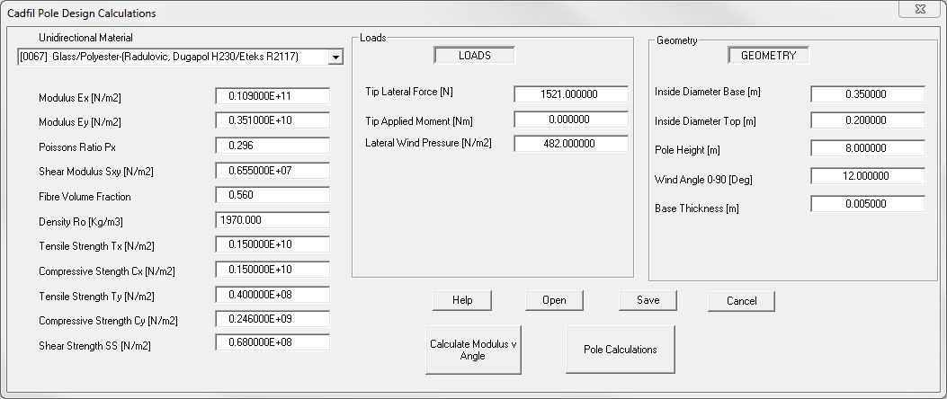
The process is a simple one, the user selects a material form the material database. The material database has stiffness, strength and other physical properties for some filament wound materials. The Database is in spreadsheet format and the user can add their own data as needed. The user enters the Pole inner diameter at top and bottom , the height of the pole, the winding angle and the thickness of the pole at the pole base. Then based on constant wind angle the inner and outer diameters can be calculated at any positioning along the pole. A number of loads can also be added including moments and bending forces at the top of the pole and a wind load pressure applied to the surface of the pole ( a variable distributed load).
The software then calculates and outputs tabulated data for bending moment and shear force , deflection, slope and physical properties at points along the pole. Other data such as the pole mass are also calculated. If a compatible version of Microsoft Excel is installed this data is output as a spreadsheet complete with data tables, results summary and graphs/charts. If excel is not installed then the data is output as comma separated values (CSV) data that can be read into most spreadsheets but this data is not formatted and has no charts. Please note that Microsoft Excel is not supplied as part of the Cadfil software.
The Pole design module does not perform stress checks in itself however for any section of the pole (the base is always the highest loaded portion) the section and load data can be entered into the Cadfil stress analysis module to evaluate stresses, strains and factors of safety against a number of potential failure criteria.
Key features
- Simple user interface via a single Windows Dialog
- Material database for strength & and stiffness parameters
- The user can add their own material data
- Simple accessible spreadsheet format for materials database
- Calculation of material properties from material database and winding angle.
- Load cases include lateral tip force and bending moment and external wind pressure
- Geometry data for the tube is height, internal diameter, base wall thickness & angle-ply angle (+/- wind angle)
- Can save and read input data via text files
- Creates a results as an Excel workbook with tables and charts that can be easy incorporated into other documents
- Calculates Tip deflection and deflected shape
- Calculates loads and section properties along the pole
- Calculates tube mass and thickness along the pole
This software is a useful tool for competent design engineers. Please note that it is the responsibility of the design engineer to ensure any design is fit for purpose, meets legal requirements, has suitable factors of safety etc. Crescent Consultants Ltd accepts no liability for the use of our software in this respect. Any critical design needs a rigorous design verification plan (including testing) to eliminate or mitigate any risks. Design standard for poles also include physical test requirements and a designer should be familiar with these.
User Interface

The left hand panel shows the material data which is selected from a list of materials in a pull down list populated from the material database. The database is in Excel CSV format and can be edited to add, delete or modify material data as required. The centre panel shows the different load cases and the right-hand panel is the geometry of the pipe, that is diameter, length, thickness and wind angle. Buttons are available to save the data, read back data saved earlier and to get help and technical information from the online help system. There are two calculation options the first calculates material properties as a function of wind angle and the second calculate Pole parameters such as stiffness, deflection and weight. Further information on Modulus and can be found following the link here.
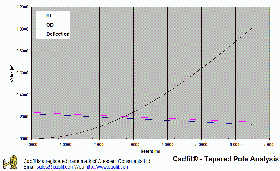
Initial shape & Deflected Shape under load

Some Sample output is shown graphed in a standard Excel template, this The inner and outer diameters (note that the thickness is increasing as the pole diameter reduces) and the deflected shape. In this case the pole is quite flexible at around 15% of the height under the loading applied.
Contact us today
If you need further information or would like to buy this software as a stand alone item or to add to an existing Cadfil package then please contact use via the link at the top of the page and we will be happy to help.
[an error occurred while processing this directive]