Dome Ended Vessel Parametric
 Cadfil Help contents
  Cadfil.com Home
Please note that this option is superseded by the Vessel With End-caps option that has more features. This Option is retained as a legacy application.
The QuickCAD application is for cylinders with dome ends and an end shaft. The programs generated are geodesic with equal end openings. This is part of the Cadfil-Lite/Lite+ package. With The Cadfil-Lite-Plus option non geodesic winding can also be made. If this option is available then put a ‘tick’ in the non-geodesic box and then you can specify the ‘opening’ diameter at the ends (the data entry box for this is made available). In this case the winding is geodesic on the cylinder and non-geodesic on the domes.
A mandrel file and a payout file for viewing and subsequent post processing is automatically created. The mandrel file can be used in the standard Cadfil Axsym program to create joining paths for wind paths created by the dome program.
The parameters are:
Two axis check box
Tick this box if winding machine only has two axes (Mandrel: AX1, Carriage: AX4) or if you only want to use two axes. The shaft and cylinder extension clearance are not needed and are ‘greyed out’ if you select this option.
Non-Geodesic Check Box (if available)
Tick this box for non-geodesic winding on the end domes. The end opening radius can then be specified at each end. Please note that this end opening radius makes allowance automatically for the width of the fibre band entered and so is the ‘true’ end opening.
Joining Path Check Box (if available)
Tick this box to create a path to join two programs together. The user must specify the start and finish positions along the mandrel. Some of the variables below will not be required and will be greyed out.
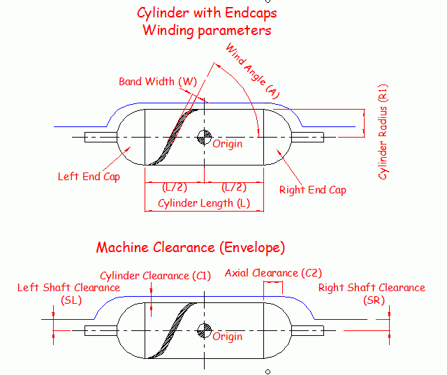
Cylinder Diameter (2xR1)
The is the diameter of the cylindrical part of the mandrel and hence of the spherical dome
Cylinder Length (L)
The length of the cylinder between domes.
Shaft Diameter
The diameter of the end shaft(s), used in the mandrel generation, these can be zero.
Wind Angle (A)
This is the wind angle in degrees on the cylindrical portion of the mandrel and is in the 0-90 degree range. Because the winding is Geodesic the Clairault equation will apply hence the condition:
EndOpeningDiameter = CylinderDiameter * sine(WindAngleOnCylinder)
Fibre Band Width (W)
The width of the fibre band used to determine the number of cycles required to fully cover the cylinder.
Cylinder Clearance (C1)
An envelope is automatically created using this and the next two parameters. This is the clearance over the cylindrical part shown in the figure higher up this page.
Shaft Clearance (SL & SR)
Clearance on the end shafts (see figure)
Cylinder Extension Clearance (C2)
The amount by which the cylindrical portion of the envelope is extended so that the winding head will clear the shoulder of the dome when it moves in at the ends (see figure).
As can be seen in the figure the datum of the mandrel is at the centre the Xdatum value must be specified in the post-processor dime to relate this position to the spindle datum.
The user can save the data as a .PAR file to retrieve latter and modify if required. The user also automatically enters the band pattern selection dialogue to choose a band pattern.
End opening X+ and X-
This option is only available if the non-geodesic check box is ticked. This allows the end opening radii (taking allowance of the band-width) to be different at each end dome. The end opeing can then also deviate from the normal geodesic end opening that occurs from specifying the wind angle on the cylinder.