Cadfil / Nastran Finite Element Analysis Interface
 Cadfil Help contents
  Cadfil.com Home
Cadfil can be used to create finite element geometry in the Nastran Bulk Data format (BDF). The data element cards) produced are MAT8, GRID, CQUAD4, CTRIA3, COORD2R and PCOMP. A detailed descriptions of these can be found in the MSC Nastran documentation "MSC Nastran 2012, Quick Reference Guide".
The Nastran Bulk data format can be reading into many programs not just MSC Nastran. For example data has been successfully imported into programs such as ANSYS/Composites Modeller and ABAQUS.
Follow this link for Details of a test case for ABAQUS
This is a link for some additional details for ANSYS
The process is very simple, the user selects the "Nastran BDF Output" option from the Cadfil main menu. You then have to select a Cadfil mandrel file (.mnd) and enter the number of elements around the mandrel. This is used to use to create the element shell geometry. Please note that the mandrel used to create the Cadfil winding patterns can be copied and modified to refine the mesh grading if required. This can be done using the Cadfil main menu mandrel edit options.
In additional to the mandrel file the user must select one or more thickness files (.TH2). The TH2 file described the thickness and winding angle along the length of the mandrel. For the mid point of each shell element the software extracts and interpolates the wind angle and thickness from the TH2 file. Which is created and an angle ply laminate with 50% of the thickness at the + or 50% at the - wind angle.
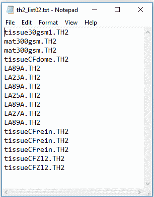
After selecting a TH2 file the software then asked to select another TH2 file for the next layers. This repeats until the Cancel option is chosen on the TH2 file selection dialog. The first TH2 file chosen will define the inner most layer of the composite and the last file the outermost layer.
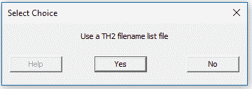
As of Cadfil V9.24 the prompt shown above is given. Rather than selecting several TH2 files the user can select a text file that is a list of TH2 file names. This is helpful to save time and input mistakes if there are a lot of layers and you make the analysis with numereous iterations and variations. An example of such a file a list is shown in the image below
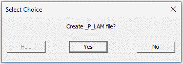
After TH2 file selection the BDF file is created. The prompt below is then given. The PLAM file is a CSV (comma separated value) file that can be read into many programs such a spreadsheets like Excel. The PLAM file is optional but is a table containing coordinate points and an angle, thickness list for each layers at that coordinate point. This data can be useful for an alternative way of getting data into an FEA program. It is discussed in more detail in the ANSYS notes but can be used with other systems where the laminate table data can be mapped onto a mesh that has been created in other software (that is, not created in Cadfil)
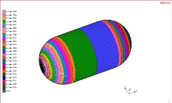
For axisymmetric bodies the laminate stack is a constant for a band around the mandrel at any particular point. Starting at the Minus X end of the mandrel the first band of element will be assign to PCOMP No 100, the next band 101 etc. Any shell elements that have no winding coverage (e.g. sometimes at the ends) get assigned PCOMP no 99 with zero thickness. And example showing the material bands is shown below
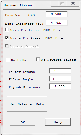
Please note that the TH2 file is created during the payout path creation (currently only for Cadfil Axsym and vessel with end caps in Cadfil Lite), this link has a description of the TH2 and THK file formats. The TH2 box shown in the dialog below must be ticked and the band width (BW) and band thickness (t0) must be set correctly. The band thickness can be estimated by using tow and resin properties if the material data button is selected from the dialog
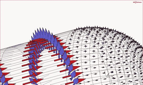
An axis system (using CORD2R) is defined for every shell element (e.g. CQUAD) as a reference for the winding angles. Element number n will have axis system number n assigned for example element number 1000 will have axis number 1000, typical axis information is shown below.
A dummy/sample orthotropic material is added to the BDF file using a single MAT8 card. The user should edit the BDF to add their own material data or should apply the material data property in the FE pre-processor being used. Cadfil creates geometry material data only the user will need to finish the FEM by adding load, restraint and other types of data as appropriate.