Overview
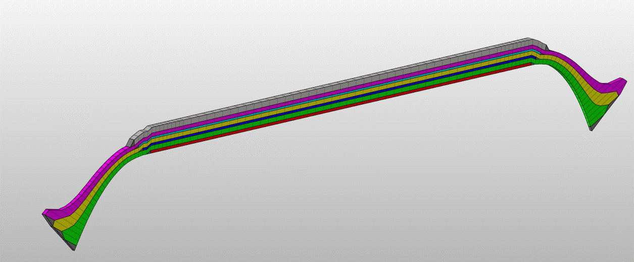
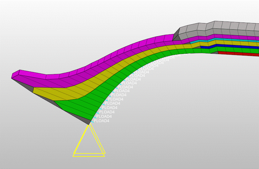
The Cyclic symmetry model has a similar formulation to thye Full Solid model and is particular good for modelling through thickness effects for thick shell filament wound structures. This type of computational models is very fast an efficient where the loading and boundary conditions on the part are axisymmetric. The CYSYM model creates a wedge shaped slice of the full model with cyclic symmetric boundary condition and this it behaves in exactly the same way as if the complete part was modelled. Typically a full model might have 180 elements around the circumference so we in the case we have 1/180 less degrees of freedom (DOF), when one considers the solution time might be proportional to the square or cube of the number of DOFSs this can lead to massive time savings. The through thickness structure of _FULLSOL and _CYSYM are identical. The models structure is built up of 8 node brick elements with one element through the thickness of each filament wound layer (FWL). Within the thickness of each element there is an angle ply laminate specified (equal plus and minus angle plies / layers). By a user option there can be 2 or 4 plies per element, +- or +--+. The 4 ply option gives more through thickness integration points and is symmetric. In some instances and systems this may give more detailed/accurate results. The power of modern computers makes use of detailed models of this kind much more feasible in terms of computation times. The formulation of the elements and the physical assumptions/approximations is dependant on the analysis system chosen and the element type/designation used in that system.


Cadfil Solver support
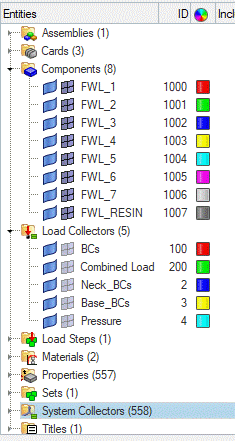
Cadfil support for shell models is primarily via the flavours pull down menu. The current selections are MSC Nastran, NX Nastran (Simcenter), Optistruct (Altair), LS-DYNA and ABAQUS. All of these generically have similar sets of model features, and the output is in the form of a native data-deck. In most cases where standard pressure loads and boundary conditions are requested data decks that are complete and can be sent straight to the solver can be created for static analysis. There is also the optional features to add Hypermesh comments to the deck that can structure the data deck for easier review and manipulation in the Altair Hypermesh software. Of course a user can load the Cadfil data deck into the Companion CAE systems that goes with the chosen solver. Examples of supported CAE systems are Hypermesh, Simulia, Apex, Patran, LS-PrePrep, Femap, Simcenter, etc etc. In such a system the user can customise the model in whatever way required, such as customised load cases, liner models, contract body analysis etc. The Cadfil interfaces in most cases try to make the FEA Engineers life easier as we pre-define node and element sets for boundary conditions, surfaces for load/contact etc. It can be tedious and time consuming setting these up by hand so pre-defining useful data sets some of what can be tedious and time consuming tasks are eliminated.
Standard Cyclic Symmetry solid Model Features for supported solver flavours.
Cadfil can produce complete standard data decks that can be sent straight to the solvers with no further work needed. Due to the different capabilities of different solver's data input modules the data decks are all different in many ways but the core features are:
- Node/grid Coordinates
- Brick element topology with 8 node
- Wedge element with 6 node, created to manage step transitions at layer ends
- Axis systems for BCs and Elements as needed
- Symmetric boundary conditions linking the side face freedoms
- Laminate Section descriptions
- Axial and tangential restraint at first polar opening
- Tangential restraint at second polar opening (if present) or at symmetry boundary if a half model
- element internal surface definition for pressure load
- Internal pressure load
- Axial Equivalent point loads at nodes on second polar opening (if present) to simulate pressure load on end boss/plug
- Individual Names Node sets for openings
- Orthotropic material data from Cadfil data base or user supplied include file
- Standard Loading/time curve/loading steps where appropriate for solver.
- Job control from supplied include file that can be user customised and optimised for needs
- Extensive data deck comments and full traceability of Cadfil FEA parameters used.
- Option for extensive Hypermesh comments to organise data in Altair Hypermesh