Overview
The shell model is the most basic form of Finite Element Analysis (FEA) model and shell elements can be utilised for effective results. for filament wound structures. Use of shell models can lead to huge computational time savings since they allow modelling of thin features with fewer mesh elements and hence degrees of freedom. With a shell model the user models in effect a surface built up of quadrilateral and/or triangular elements and the thickness is described (in Cadfil) as a series of layers with material, thickness and fibre direction that build outwards (layer one is on the inside). The power of modern computers makes use of shell models to save time less of a justification to using more computationally expensive models, however when a user wishes to analysis a large number of variations looking for optimal solutions this may be an effective solution. The formulation of the element and its physical assumptions/approximations is dependant on the analysis system chosen and the element type/designation used in that system.

Cadfil support
Cadfil support for shell models is primarily via the flavours pull down menu. The current selections are MSC Nastran, NX Nastran (Simcenter), Optistruct (Altair), LS-DYNA and ABAQUS. All of these generically have similar sets of model features, and the output is in the form of a native data-deck. In most cases where standard pressure loads and boundary conditions are requested data decks that are complete and can be sent straight to the solver can be created for static analysis. There is also the optional features to add Hypermesh comments to the deck that can structure the data deck for easier review and manipulation in the Altair Hypermesh software.
In addition there are some specific options that create shell models for ESACOMP and for ANSYS via the HDF5 (.h5 file) Composite CAE specification. These are discussed specifically in separate sections below.
Using imported FEA geometry.
Cadfil can as import basic FEA geometry (nodes and shell elements) that is geometrically compatible with and existing filament winding data set and add the Material, thickness, fibre architecture and boundary conditions. The imported model can be made of tris, quads or a mix. This method is useful where the analysis requires some specific mesh detailing. A common applications is tanks that have a number of holes for side ports. Cadfil will find all such holes and create named node sets. Openingings that correspond to circular end ports will get standard boundary conditioned added, all the features listed below are supported. Models supported for import include Nastran bulk data decks and LS-DYNA keyword decks.
Standard Shell Model Features for supported solver flavours.
Due to the different capabilities of different solvers data input modules the data decks are all different in many ways but the core features are: Cadfil can produce complete standard data decks that can be sent straight to the solvers with no further work needed.
- Node/grid Coordinates
- Shell element topology, 4 node Quads and/or 3 node tris
- Axis systems for BCs and Elements as needed
- Laminate Section descriptions with global ply IDs where supported
- Axial and tangential restraint at first polar opening
- Tangential restraint at second polar opening (if present) or at symmetry boundary if a half model
- element surface definition for pressure load
- Internal pressure load
- Axial Equivalent point loads at nodes on second polar opening (if present) to simulate pressure load on end boss/plug
- Individual Names Node sets for openings
- Orthotropic material data from Cadfil data base or user supplied include file
- Standard Loading/time curve/loading steps where appropriate for solver.
- Job control from supplied include file that can be user customised and optimised for needs
- Extensive data deck comments and full trackability of Cadfil FEA parameters used.
- Option for extensive Hypermesh comments to organise data in Altair Hypermesh
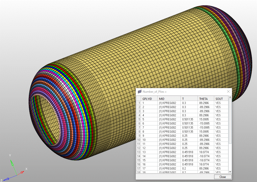
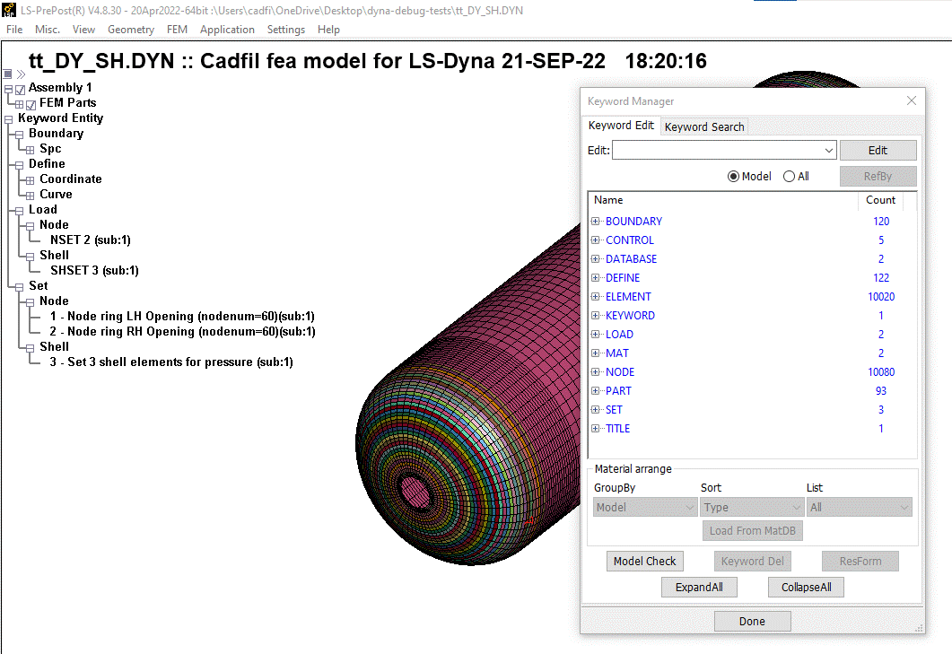
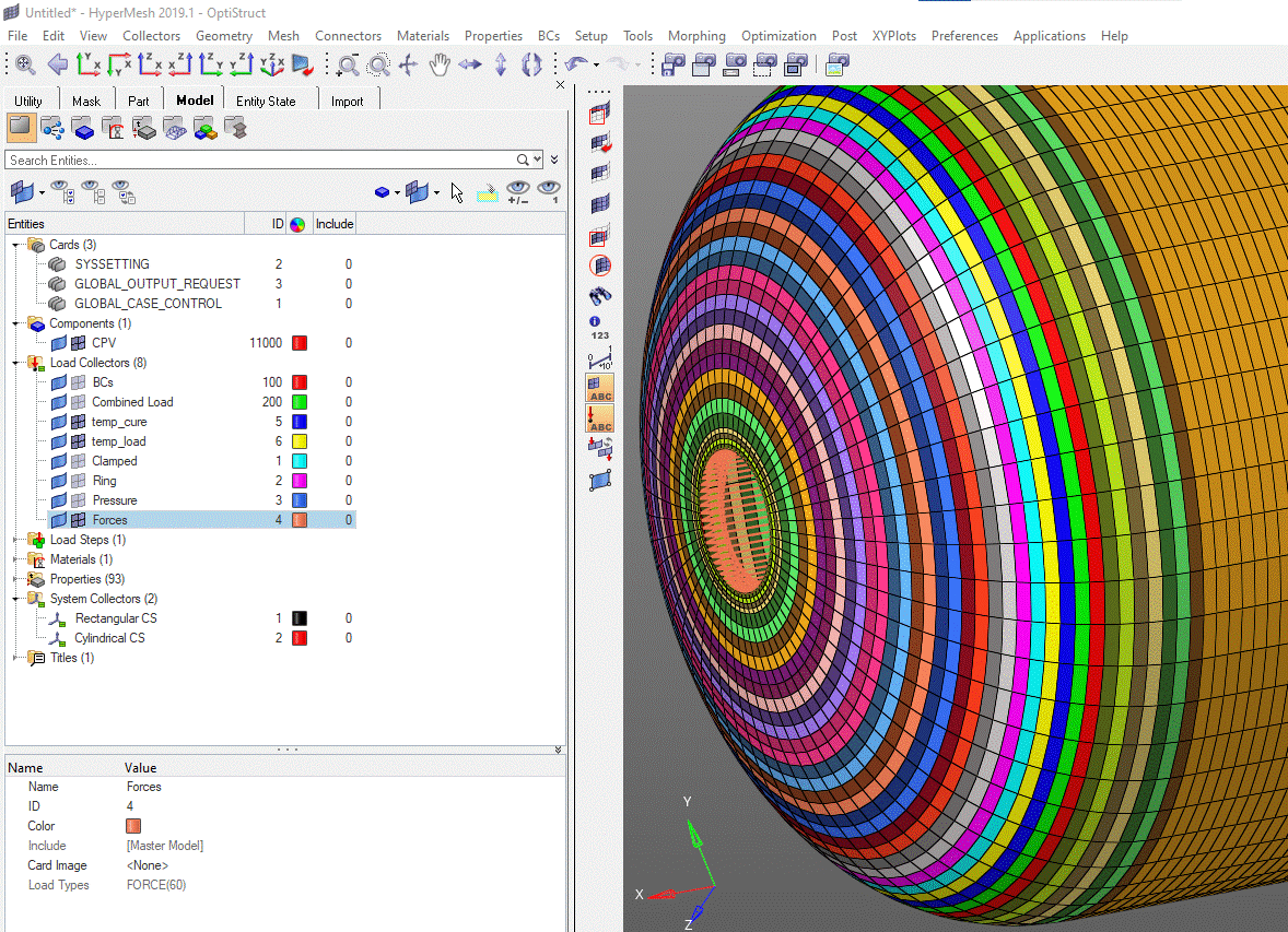
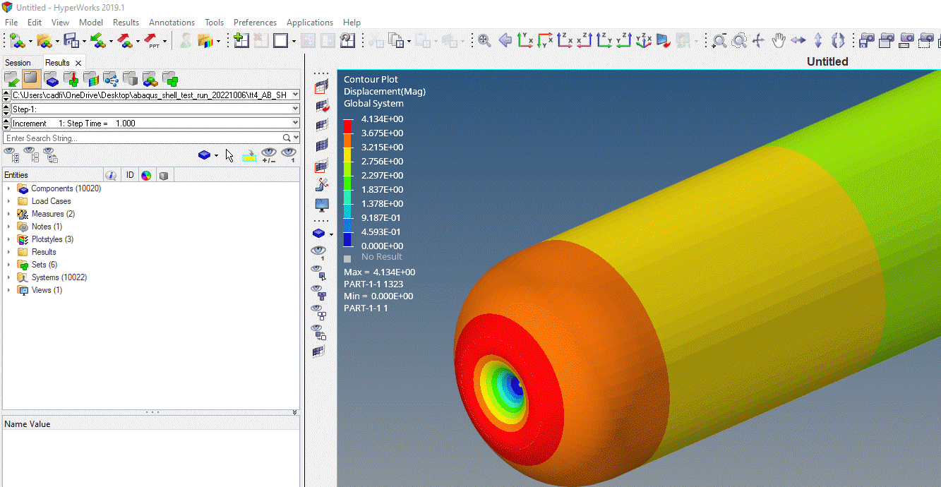
The figure below show Cadfil Shell model data for different systems, in a range different CAE systems


