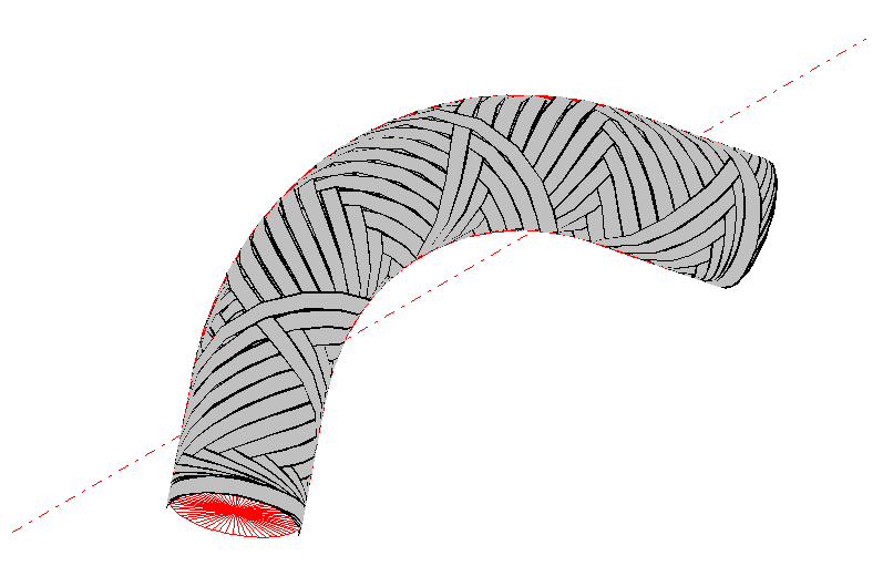
Cadfil Elbow quickly generates full winding paths, both helical and hoop, for pipe bends. Please note that the Multi-Bend Ducts (MDB) option is more flexible and can do anything this option can, and more, and is included as part of the elbows package. Convex and concave arcs can be fitted between data positions and edited as required, the software package works for helical or hoop winding over total length or in local zones, and a mandrel can be defined through mandrel editor or through IGES (or parametrically in the case of elbows)
The Cadfil Elbow winding software can be purchased as part of the Cadfil-Axsym package or as a stand-alone module. In either case all the advanced graphics features of the Cadfil package are available for displaying machine positions and viewing winding paths.


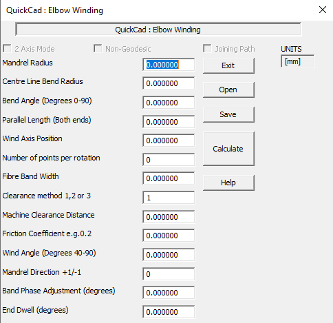
In the elbow parametric option, programming could not be easier! The user enters data such as the pipe diameter bend radius, fibre bandwidth, wind angle etc. The data is saved as a file and can be recalled and modified at will. The mandrel surface definition and full coverage winding patterns are then automatically created.
The path is then post-processed to generate machine control data. Numerous control options can be set dependent on the axes available on the machine. Different speed control options can be set to reduce winding time or limit axis accelerations. The software calculates the winding time. Modules for out-putting data for Finite Element Analysis can also be supplied.

Cadfil is supplied configured for the customer’s winding machine. Cadfil can be supplied with multiple machine configurations, the user just selects which machine to use. Cadfil can be configured for 2 to 6 axes and for all filament winding machines types and control systems.
A Cadfil Elbow winding case study - Thermoplastic winding
The embedded mpeg Video (12MB) may be slow to load or may not play due to browser settings. An alternative video can be played by following this link to YouTube (opens new window).
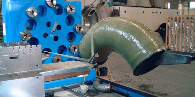
In this example, the customer wished to over-wind an aramid (Kevlar) thermoplastic tape onto a steel pipe bend. To productionise this for volume manufacture, a special winding machine was the best solution. It was necessary to first undertake product proving on an existing winding machine, without having to make costly modifications. The machine is a 6 axis BSD filament winding machine with a Siemens CNC controller; the winding took place at the BSD factory in Germany. As you will see in the video, the tape was heated to melt the surface using a gas jet, mounted close to the mandrel to prevent tape chilling.
There were some interesting software challenges for CADFIL. Firstly maintaining the angles in 3D that the tape is presented to the gas burner and achieving a constant speed that the tape is passing through the flame. Both are required to get the correct tack level without 'over cooking' the tape. As the mandrel is eccentric to a variable degree, the speed the tape is leaving the spool is not the speed it is passing through the flame.
Secondly it is possible to wind an elbow using a 4 axis machine. Unfortunately in this case, the winding machine had insufficient cross-feed axis stroke for the diameter and eccentricity of the mandrel. The solution was to disconnect and remove the eye-roll axis (not required for this part) in order to create more clearance, and then to use both the cross-feed and vertical axes simultaneously as a composite cross-feed axis. The combined axis strokes give a larger, effective, composite axis stroke on an inclined plane. Because of this requirement, there is some comprise on maintaining the gas burner position in a couple of places such as at middle of the part,near top dead centre, where the flame touches briefly on the mandrel surface as the machine is at the limits of travel on two axes.
Using Cadfil software, it was possible to meet these challenges and to achieve accurate tape placement. The final software solution in Cadfil was very simple to use, once the additional constraints of the machine had been identified and configured into the Cadfil NC post-processor.
