Cadfil Finite Element Analysis Interface Module
 Cadfil Help contents
  Cadfil.com Home
Links Sub-topic on this Page and related pages
- SHELL model with Cadfil Mesh
- SHELL model imported Mesh
- ESACOMP Full Shell/laminates
- Nastran BDF 2D Axisymmetric
- SOLID Slice with Cyclic Symmetry(_CYSYM)
- TH2 Files refactored
- Refactored thickness angle table, T1
- Refactored thickness angle table, T2
- IGES file curves for T2 Table
- Grid Points/Laminate Table (_PLAM)
- Nastran BDF MAT8 angle-ply table
- Shell model Via Continuous Grid Mapping Method
- Shell model Ansys/HDF5 format
- Cadfil FEA Interfaces data input fields
- Full Solid Model (_FULLSOL)
Cadfil FEA Interface Overview
Cadfil can be used to create finite element geometry and data for import into a wide range of FEA Analysis packages. On a doubly curved surface such as a pressure vessel dome, the angle and thickness are continuously variable. With multi-layer windings it is both difficult and time consuming to create fibre architecture in analysis packages. Cadfil offers a number of powerful FEA interface solutions. Customers successfully produce Cadfil data for use in Nastran/Patran/FEmap/Hyperworks/Optistruct/LS-Dyna/ESACOMP/ABAQUS and ANSYS as well as other system. Cadfil deals with winding geometry and fibre architecture and in many cases can create boundary conditions, load cases, contact surfaces and other useful FEA modelling data structures. It is possible to specify Orthotropic material data directly from the Cadfil database which is open for the user to add or remove materials as needed. For Nastran family system this topic shows the different cards that are directly supported by Cadfil for each system. The user can of course use their own material data by using a text based include file of their own design and specification to suit the modelling system being used.
The models types break down into a number of categories, SHELL models (a surface type model with a laminated 2D shell elements), SOLID models (continuum models) with 3D Brick or wedge element types that have either laminated properties (thick shell) or per layer 3D orthotropic properties. For more information on the different types of FEA model that can be produced by Cadfil, please see the FEA Model types page. A third type of data includes angle/thickness table data or data list files that can be used in systems that can import and map data to their own models or where a user uses their own bespoke pre-processing tools.
A list of some if the data file types that can be produced direct from Cadfil is:
- BDF/DAT/NAS/FEM Nastran bulk data type data deck formats used with MSC-Nastran(APEX/PATRAN), NX-Nastran (Simcenter/FEMAP), Optistruct/Multiscale(Hypermesh). In addition optional Hypermesh comments can be added to data decks to group, collect and organise data entities.
- INP Keywords datadeck for ABAQUS(Simulia)
- DYN/K Keywords datadeck for LS-DYDNA (LS-PrePrep)
- H5 Shell model in HDF5 format to the ANSYS "HDF5 Composite CAE Specification".
- csv Comma separated value for for Excel and similar systems, the separator character can be customised to meet local (world region) settings.
- th2 Cadfil thickness file format, these can be refactored to a modified (common) base data discretisation.
- igs IGES CAD file (layer long section profiles for outer shape)
- ESA ESACOMP has no specific file type extension. Cadfil creates a folder based on the job name and creates files mesh.elements and section.data in that folder as per ESACOMP expectations.
The FEA interfaces can be found in the Analysis (FEA) Output option on the Utilities menu. This creates the dialog shown below. Note that where 'jobname' is used in this topic it refers to the name taken from the "FEA Data Output Name" text box. In the picture below 'JobName' is '3D_AB'.
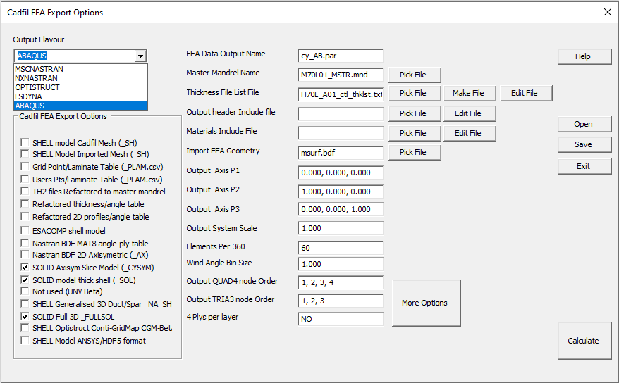
At the top left is the Flavour pull down menu, the options currently are NXNASTRAN, MSCNASTRAN, OPTISTRUCT, ABAQUS and LSDYNA, at Version 9.73 the flavour option supports Shell model (_SH) both imported mesh and Cadfil mesh, SOLID model outputs (_SOL and _FULLSOL) as well as the SOLID cyclic symmetry model types (_CYSYM). In all these cases the options can be used to modify the output, but not all options are relevant to all types.
On the left of the dialog a set of tick boxes for the different types of output that can be created. There are some data input field in the middle section of the dialog (and some others under More Options) and some action Buttons to the right side. The Process is to pick the type(s) of output needed using the tick boxes, populate the data boxes, save the data and then click 'Calculate to create the output files'. In general ones you have a set of Options to use with your chosen analysis systems most of these will not change so for the next design iteration you open the old JobName.par file change a couple of input items and than save under a new JobName.
On the right side there are some action buttons, Help to show this topic, Open to read a parameter file that has the data and tick box status for all the entries on this dialog that has previously been saved using the Save button. Exit quits without doing anything and Calculate validates the data entered and then creates the output files requested via the tick boxes. The output options are Briefly Described Below and there is further detail in other associated help pages. An overview of the elements types and default topologies that can be output can be found here.
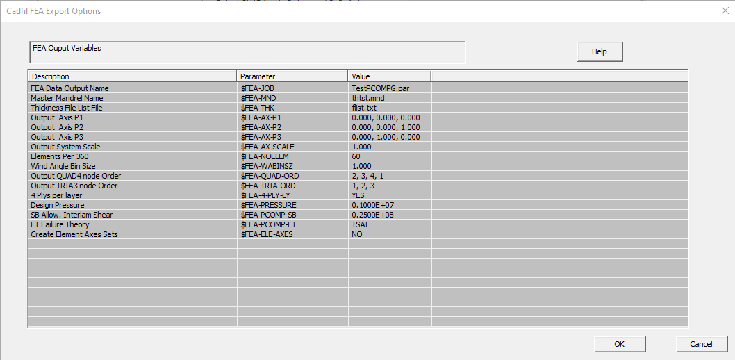
The input value boxes list has kept growing in number as more options have been added which has become unwieldy. The More Options button pops the list box shown below where all the input values can be found as well as additional ones. You may find more options described below than are on the picture as there is no real need to keep updating the pictures after every change. To modify a value click on the line in the data table to get an edit box. Note that it is likely that you will see a scroll bar to the right of this dialog because there are more options than fit on the screen!
Setting Material data
Each thickness th2 file refer to a material number e.g 1 or 2 etc. These material index numbers can be connected to a set of material properties for stiffness and strength in the Cadfil material database . This is described in a separate sub-topic on setting material data.
Please note that you can select multiple types of output by ticking more than one tick box , however the three varieties of full shell model (Cadfil Mesh Nastran, Imported Mesh Nastran and ESCACOMP) are incompatible and mutually exclusive if you pick more than one of these you will only get output for one of them. There are same options (HDF5 and CGM) that are exclusive and cannot be used with other options.
SHELL Model Cadfil Mesh
This creates the data output file 'jobname'_SH.'EXT', where the file extension is set in the options, if not set the defualt extension is '.BDF'. This option creates a surface shell of elements with a laminate stack created for each element. The Element resolution in the axis direction is taken from the mandrel file specified in the "master mandrel" edit box and the element resolution around the circumference is taken from the "Elements per 360" edit box. The Nastran data cards produced are MAT??, GRID, CQUAD4, CTRIA3, COORD2R, PCOMP/PCOMPG, SPC1,SET3, PLOAD2, FORCE, SPCADD and LOAD and others. Native data deck cards produced also for ABAQUS and LS-DYNA if those flavours are selected. For normal winding programs the laminate is created for each layer with an angle ply laminate with 50% of the thickness at the + and 50% at the - wind angle. Is is also possible to output each winding layer as 4 plys with 4x25% of t at +--+ angles to make a symmetric stack. A detailed descriptions of these can be found in the MSC Nastran documentation "MSC Nastran, Quick Reference Guide" or in the Siemens NX Nastran reference.
For axisymmetric bodies the laminate stack is a constant for a band around the mandrel at any particular point. Starting at the Minus X end of the mandrel the first band of element will be assign to Property ID 100, the next band 101 etc. Any shell elements that have no winding coverage are not output. The user can create manual layers for isotropic or orthotropic material a common case being the thickness of a liner or additional rib reinforced areas the cylinder with woven material.
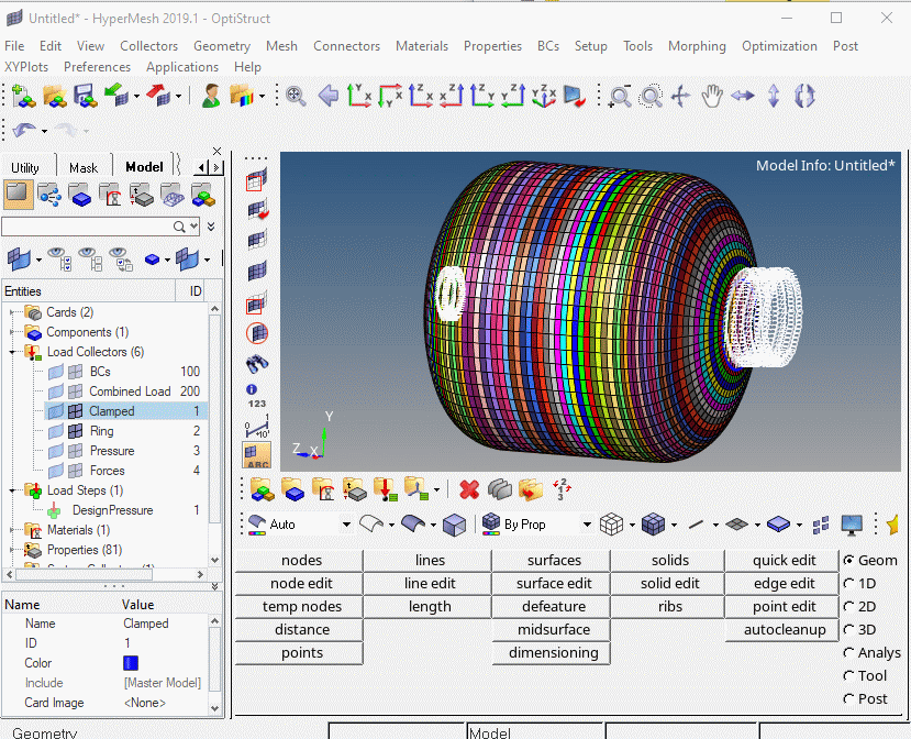
The standard output case has BC's (boundary conditions) with fixed nodes around the opening that is at the "fill end" and radial restraints with axial freedom if there is an opening at the other end of the bottle. A pressure load is applied to the surface and if there is a hole at the base forces equivalent to the pressure load from the hole are applied. For solvers that natively support bulk data such as MSC Nastran, NX Nastran or Altair Optistruct this data deck can be sent straight to the solver with no human touch. Such a mesh is shown below imported direct into Altair Hypermesh
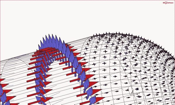
An axis system (using CORD2R) can be defined in Cadfil for every shell element as a reference for the winding angles or these can be referenced to a single master axis. In the first case Element number n will have axis system number n assigned for example element number 1000 will have axis number 1000, typical axis information is shown below.
A sample orthotropic material is added to the BDF file using MAT8 card for each orthotropic material index number found in the th2 files. Alternatively the user can select specific materials from the Cadfil database. The user can also edit the data deck to cut and paste their own material data or indeed modify the material data property in the FE pre-processor being used.
Imported Mesh Nastran BDF Shell/laminates
In the first option discussed above Cadfil create the FEA mesh, but consider a more general case like the example below where a pressure tank has cut-outs in the side wall for pipe entry or other features that would not be part of the winding process. This mesh has been created in an FEA pre-processor software, ensuring the geometry and axes are the same we then create winding programs on a matching Cadfil model but without the cut-outs. We can then import via bulk data the grids and elements for the mesh an apply the laminates from the winding paths created in Cadfil. Note that imported mesh is no longer a separate option at V9.73, an imported mesh is used if a file name is given in the imported mesh option box otherwise the CAdfil internally generated quad mesh is used.
The Picture below shows the same mesh after import to Cadfil and the properties have been applied. This model is then imported back into the FEA system to make a final model as Cadfil has no concept about what the boundary conditions and loads might be around the cut-outs and indeed the user may wish to model the pipes and flanges. Cadfil does created boundary conditions sets around each of the apertures but only as an aid if that is helpful. An example of the work flow and general principles involved in such an example can be found in this external link to a pdf.
ESACOMP Full Shell/laminates
This option produces output that can be used with the Altair ESAComp(TM) software, a system for the analysis and design of composites. The output model is similar to the Cadfil Mesh Nastran BDF Full Shell/laminates option. Three output files are created, 'section.data', 'mesh.nodes' and 'mesh.elements'. Because ESACOMP is expecting fixed file names Cadfil creates a folder 'Jobname'_ESCOMP_SH for these files so the are unique to the job. The first file contains 'sections' that detail the laminate stacks (angle and thickness for each laminate section referenced in the elements file), the second file is point (grid/node) data and the third contains element topologies. The user can edit the 'section.data' file to change the ESACOMP material index/indices to the materials they have setup in ESACOMP, it is also possible in ESACOMP to map a material to the material number used in the Cadfil output. The design for design is taken from the input box on the Cadfil FEA dialog, The burst may need to be changed from the sample values supplied in the file. The ESACOMP output also creates restraints on the two open ends of the winding. One end is fixed and the other constrained to be planer but to allow axial motion. A distributed axial load is also place on the end opening that is equivalent to the pressure load on the material that would close the opening. The design pressure load is also applied to the inside of the vessel. Thus the data deck from Cadfil can be run in ESACOMP with no modification needed if required.
Nastran BDF 2D Axisymmetric
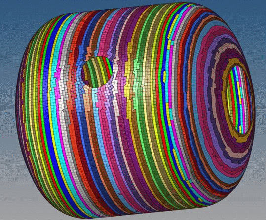
This option is largely obsolete and will be withdrawn in the future, use the cyclic symmetry option. This creates the output file 'jobname'_AX.BDF . A 2D model of a longitudinal section is created with planar shell elements. In an FEA system this 2D section could be rotated about the axis to produce a full 3D solid elements mesh or could be used in an Axisymmetric analysis if the loads and constraints are also rotationally symmetric. This type of analysis is very efficient for thick wall pressure vessels. The various layers and of the winding and elements within are given PSHELL identifiers that reflect the +/- angle ply and physical material for that element. An axis for the principal material direction for the angle-ply is created for each element. The Nastran data cards created are MAT1, GRID, CQUAD4, COORD2R and PSHELL. Users have used this type of file with the ABAQUS system using the Winding Plugin.
The Above image shows a 2D axisymmetric model based on three winding layers, two low angle helical layers of slightly different base wind angle and extent and a double hoop layers on the cylinder part. The colour coding is showing different PCOMP (material) entries for different groups of elements.
3D SOLID Cyclic Symmetry(_CYSYM)
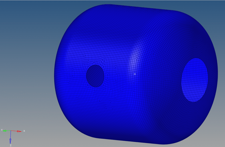
The 3D Cyclic symmetry model is the most complete and detailed stress calculation for thick walled analyses. The Picture below shows a model for a thick wall pressure vessel (700 Bar hydrogen tank) This has 35 Filament Wind layer entries (FWLs) many containing multiple sub-plies. The output is controlled largely be the Output Flavour selected but can be customised by the some of the options. Whilst the description below is focused on NAstran type data decks, native LS-DYNA and ABAQUS decks can be made also.
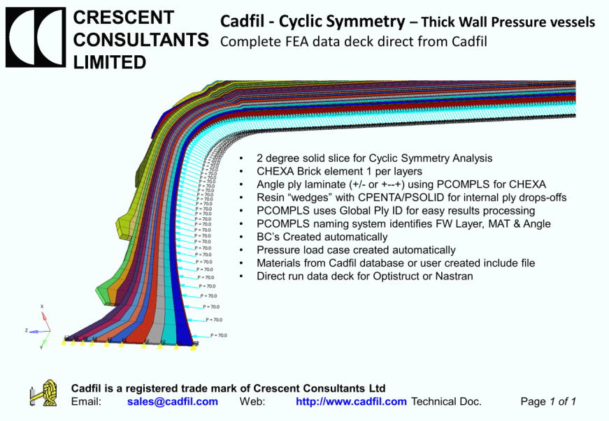
The model is based on a 2 degree solid slice made of CHEXA Brick elements with 1 element per layers (FWL). Within each element we have an Angle ply laminate (+/- or +--+) using PCOMPLS (or PCOMPS) including consistent use of Global-Ply ID's. Resin “wedges” with CPENTA/PSOLID a rev automatically created for internal ply drops-off's. PCOMPLS uses Global Ply ID for easy results processing PCOMPLS naming system identifies FW Layer, MAT & Angle. BC’s Created automatically at any end openings. A pressure load case created automatically. Materials are from Cadfil database or user created materials include file. The data-deck produced can be run directly data deck for Optistruct or Nastran or can be read into a pre-processor system such as Hypermesh or Patran. The discretisation along the part can be adjusted by means of the FEA-AX-XSTEP parameter, car must be chosen with this as if is is too course the shape detail as ply drop-off's lost. Too fine and the model become massive! Consideration of the ply thickness should also be made. The model in the picture has a mesh grade of 2.5mm. The resin wedges are set as material 99 but the user must supply a resin material property either by editing the deck or using a material include full that has a MAT1 (isotropic ) card for material 99.
TH2 Files refactored
The "thickness file list file" edit box contains the name of a text file whose contents are a list of TH2 thickness files that are for the layers of the full winding sequence. An example of such a file can be seen in the picture below. These thickness files are 'refactored' to create files 'JobName'001.TH2,'JobName'002.TH2,'JobName'003.TH2,... To explain further, within Cadfil you create a mandrel surface and then create a winding pattern on that surface. One of the outputs of that process is a thickness description in the 'TH2' file. The format and layout of the TH2 file can been seen in the linked topic. The file is basically a table of X, R, Angle, t/t0, Slope, ( axial and radial position XY in effect, winding angle , thickness as a multiple of the ply thickness and the slope angle in degrees of the mandrel axial section profile). When winding a thick part such as a pressure vessel it is often necessary to redefine the mandrel surface for later windings. Unfortunately adding the thickness of one layer to a mandrel to create a new mandrel does not work well because the wound surface has some small steps, bumps and discontinuities in the turn zones. Using such a surface will not create good winding programs because there will be discontinuities in the paths that make the machine motion erratic. The solution is to change the parameters for the domes to reflect the approximate effect of the thickness. A problem with this is that when you have a series of TH2 files for a series of layers there is no longer and obvious correlation between X,R positions from file to file to allow the overall multi-layer laminate to be constructed. What this option does is take a series of points along the master mandrel surface and then looking normal to the surface of the master mandrel finds the corresponding position in the profile of each of the TH2 files. It then interpolates the thickness an wind angle at that point. The refactored TH2 files have X,R coordinates that reflect the surface profile after the previous layers have been applied. All the new TH2 files have the same number of points and there is correspondence between positions, for example line 3 in the table is the same location in all the files. Refactored thickness files can be used by external processes to apply fibre architecture, for example these can be read into the ABAQUS winding plug-in. Note the the base geometry on which all the thickness files accumulate is that of the master mandrel that is specified.
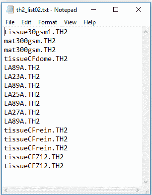
Note that in the thickness file list above some layers have been repeated for example "mat300gsm.th2" is shown twice. The Cadfil software has been updated so that instead you could now have "mat300gsm.th2,2" the ",2" indicating it is included two times and will make two separate sets of filament wound layers in the output models.
Refactored thickness angle table, T1
This creates the output file 'jobname'_T1.csv. This is a comma separated value (CSV) table that can be read into excel, such a table data can be applied copy/paste into an FEA system and then referenced. ANSYS Pre-Prep has such a facility. The Table headers are "x r slope Angle1 thick1 Angle2 thick2……". X,R and slope refers to the master mandrel and then there area thickness and angle entries for each layer. Thickness can be zero and please note that the thicknesses are multiples of the PLY thickness t0. The t0 and material index number can be found at the bottom of each TH2 file.
Refactored thickness table, T2
IGES file curves for T2 Table
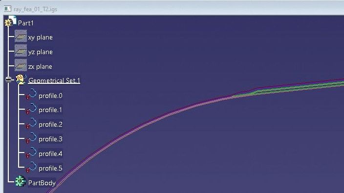
This creates the output file 'jobname'_T2.csv. This is a comma separated value (CSV) table that can be read into excel, such a table data can be applied copy/paste into an FEA system and then referenced. ANSYS Pre-Prep has such a facility. The Table headers are "N X0 Y0 Z0 X1 Y1 Z1 X2 Y2 Z2,.....,Thick0 Thick1 Thick2,..... N is the line number starting at 1, the (XYZ)i are the points that are the outside after layer i has been placed/wound (i=0 being the mandrel). The true layer thickness are the Ti values. The XYZ are planar so typically all the Z values will be 0.0. This option also creates the output file 'jobname'_T2.igs which contains polyline curves (composite curve of line segments) for the mandrel profile and curves for the complete outside profile after each filament wound layer (FWL). These are 2D curves (Z=0) to the Cadfil axes, origin and units and can be imported into many CAD or FEA systems. An example picture of a set of curves for a dome ended vessel with several layers of helical and hoop winding is shown below after import in the Catia CAD package.
Grid Points/Laminate Table (_PLAM)
User Points/Laminate Table (_PLAM)
This creates the output file 'jobname'_PLAM.csv. This is a comma separated value (CSV) table that can be read into excel, such a table data can be applied copy/paste into an FEA system and then referenced. ANSYS Pre-Prep has such a facility. Note that these two options are very similar, you should select one or the other but not both, if both are selected you will get the former only. The PLAM file is optional but is a table containing coordinate points and an angle, thickness list for each layer at that coordinate point. This data can be useful for an alternative way of getting data into an FEA program. If you chose the user/points option you will be asked for a file name. The file chosen should be a comma separated value file. The file contains a list of coordinates with the format ID,x,y,z. So, if the part had ben meshed to include various non-axisymmetric features such as supports, ports and bosses the user could export the coordinates of the centre of each element in the mesh for which the laminate description is needed. Cadfil then create the table with ID, coordinate and thickness angle for all the points the user specified. The ID then gives the laminate an association to the original mesh. This option is discussed in more detail in the ANSYS notes but can be used with other systems where the laminate table data can be mapped onto a mesh that has been created in other software (that is, not created in Cadfil). Such mapping facilities have been created to import data from external processes such as draping simulation.
Nastran BDF MAT8 angle-ply table
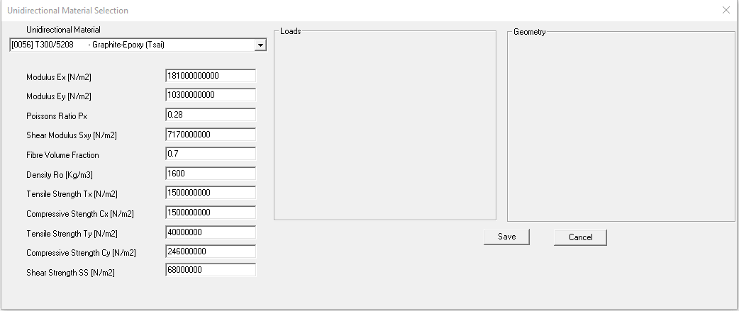
This creates the output file 'jobname'_MAT8.bdf. This file is a Nastran bulk date with orthotropic material properties (MAT8 data card) for a series of angle ply laminates, so for example if the Wind Angle Bin Size were specified as 1 degree than 91 property entries would be created for angle ply laminates of +/-0, +/-1, +/-2,..... +/-87,+/-88,+/-89, +/-90. These are calculated using classical laminate theory from properties specified for a unidirectional composite. A Start Material ID Number is requested, so in this example if 1000 was entered then material ID's (MID's) created would be for material 1000 through to 1090 (91 entries). The material DBF can be imported into compatible system or can be applied by Cut/Paste into another BDF file.
The Unidirectional material selection is shown below. The Data comes from and excel sheet database in the Cadfil install folder. The User can enter their own material data but some sample material is supplied. You select the material required from the dropdown combo box and it then populates the dialog, clicking the save button selects that material data and then exits.
Shell model Via Continuous Grid Mapping (CGM) Method
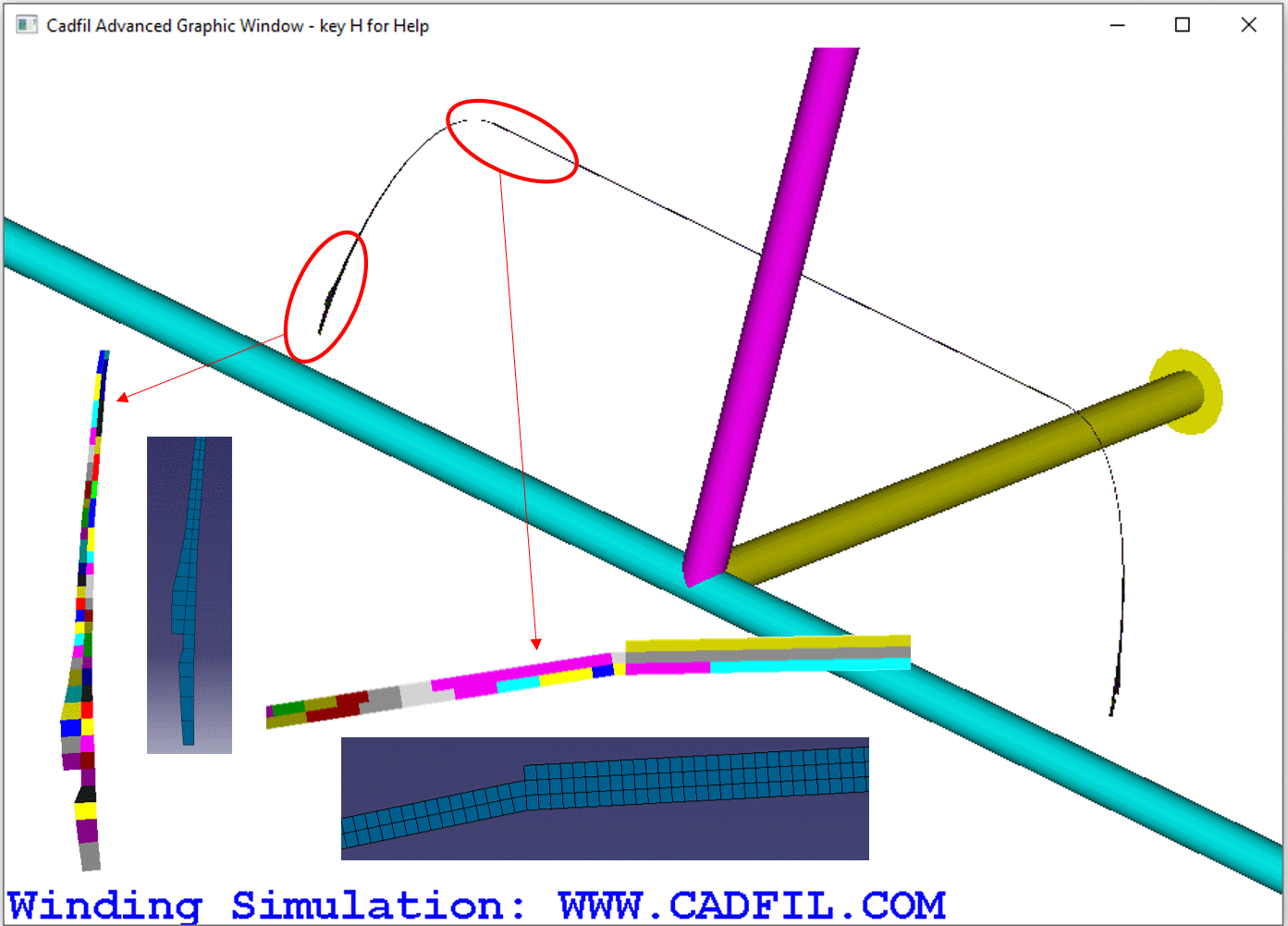
This is a entirely new methodology for FEA model creation based on new technology introduced in Cadfil V9.66. All previous models are based on thickness files (TH2) which have calculated (for each filament wound layer) an average thickness for each axial position along the mandrel. This thickness file method is applicable only to rotationally symmetric parts. With all FEA methods some approximations are required, for example a geometry is approximated as being represented by a collection of elements of uniform property. The averaged (uniform) thickness is for the most part a reasonable assumption but is not necessarily reality. A winding layer is in fact a series of bands that are placed on the surface of the mandrel. If we consider the band (like a tape) of having a width and a constant thickness (t0) then at any point on the mandrel the thickness will a whole number (1, 2, 3,.... N) multiple of t0. Consider the three picture shown below. The in the new technology method you can see a complex variation of thickness on the dome as the bands progressively overlap more an change direction. The new technology is based on processing path files (.pay) sequentially laying the bands as they are during the actually winding and accumulating the thickness and direction information as it goes. As such, this method can process non-axisymmetric paths and can also include the material laid down in single transition (joining paths). Because the fibre structure is much more realistically represented than with using a traditional laminate description a suitable FEA system can much more accurately represent the the fibre structure and use multi-scale approaches for more accurate prediction of failure.
This option is discussed in much greater detail in the topic New Technology FEA (Continuous Grid Mapping)


Shell model Ansys/HDF5 format
This outputs a shell model conforming to the Ansys HDF5 specification for import into Ansys CAE. More detail on this can be read in the HDF5 Composite CAE Specification . A workflow is published by Ansys in the Ansys technical help documentation.
Cadfil FEA Interfaces data input fields
FEA Data Output Name This box contains the jobname that is the root of any files names created by the FEA interface. The Open button is used to load previously saved data that is in a .par parameter file, and the parameter file name becomes the jobname.par. This jobname.par is it is also used by the SAVE option that saves all the date entered.
Master Mandrel Name Many of the FEA options use thickness files (.TH2), each thickness file will have been associated with a mandrel profile from a mandrel file. Where a full shell model is being created the elements sizes and resolution that are good for program generation might not be ideal for an FEA model. A mandrel can be modified to refine the mesh grading if required using the Cadfil main menu mandrel edit options.
Thickness File List File This input box contains the name of a text file that is a list of thickness files. The list file must contain the names one or more thickness files (.TH2). The TH2 file described the thickness and winding angle along the length of the mandrel. As of Cadfil 9.67 this box can alternatively contain the name of a combined winding file (.ctl). This works in two ways, if the new Grid Mapping (CGM) option is used this works directly with payout (.PAY) winding files. A .ctl file is a list of payout files and also includes other information such as how many times each layers is repeated. If a combined winding (.CTL) files is specified with other options that require thickness (.th2) files then Cadfil will try to open a default thickness list file. The default thickness file associated with <file-name>.ctl is <file-name>_ctl_thklst.txt. Note that as of Cadfil 9.67 the Combined winding editor ( See the Topic Control (.CTL) File for combining winding paths) automatically creates a default thickness list file when you save, this option only applies if the Cadfil systems has the FEA options enabled for use. If the default thickness list file is not found or any of the files referenced by the thickness list file or the .Ctl file are not found then error messages will be given.
The Pick File button allows an existing list file to be selected using a standard window file open/selection dialog. The Make File button opens a standard windows file open dialog and the user can then click an existing th2 file and then click OK (or to be faster double-click the file), the file dialog remains and then another th2 file scan be picked in the same way. When the selection of TH2 files is complete click the CANCEL button on the file selection dialog. You will then be asked for a name of a (.txt) file to save the list to and after the list file is saved the file name is automatically placed in the Thickness File List File data box. There is a third button Edit File which opens the list file in the windows text editor (normally Notepad) for manual editing or viewing if needed .
As discussed about the thickness list file is a list of th2 thickness files with one file name per line. If you open a th2 file in a text editor you will see by default that all the thickness files refer to material index "1". You could edit some of the files to refer to a different material for example material "2". Later you get the option to map each material index to an actual set of real material properties. It is also possible to edit a th2 list file to add a repeat number and material index that will override the material index actually in the file. A line file1.th2 could be changed to file1.th2,2,3 to repeat the layer 2 time and apply material index 3, the line file1.th2,,3 would repeat the default number of time (1) and use material index 3. If no material index is specified (or zero) then the value in the actual th2 files is used as normal.
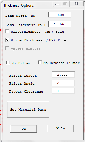
Note that the TH2 file is created during the payout path creation (currently only for Cadfil Axsym and Vessels with end caps in Cadfil Lite, and Multi-Hoop and now also for Pipe/Multi-Pipe), this link has a description of the TH2 and THK file formats. The TH2 box shown in the dialog below must be ticked and the band width (BW) and band thickness (t0) must be set correctly. The band thickness can be estimated by using tow and resin properties if the material data button is selected from the dialog
Header Include file This is used for options where Cadfil creates and an output model based on bulk data such as for Nastran, Patran, Femap, Hypermesh, Optistruct,.... In these cases there are job control instructions for the solver that become before the first bulk data entry. This option value is the name of a text file whose contents will be added to the top of the bulk data. A user can make their own file or copy and edit edit some of the examples found \Cadfil\cafil9xx\Data folder. The header txt file should be in the same folder as all the other input files being used. This entry can be left empty if no header file is required. An example header is shown below for the Altair Optistruct solver. For the standard bulk data output from Cadfil that has materials restraints and pressure loads with this header the output deck can been sent straight to the Altair Optistruct solver which will then do a linear static analysis creating the defined results sets.
$$------------------------------------------------------------------------------$
$$                  OPTISTRUCT HEADER INCLUDE FILE START                        $
$$                 Optistruct Input Deck Generated by Cadfil                    $
$$                             www.Cadfil.com                                   $
$$------------------------------------------------------------------------------$
OUTPUT,OP2,FL
CSTRAIN(H3D,NDIV=3) = YES
CSTRESS(H3D,NDIV=3) = ALL
CFAILURE(H3D,NDIV=3) = ALL
ELFORCE = ALL
$
$$------------------------------------------------------------------------------$
$$                      Case Control Cards                                      $
$$------------------------------------------------------------------------------$
$
$HMNAME LOADSTEP               1"DesignPressure" 1
$
SUBCASE        1
  SPC =        100
  LOAD =       200
$
$$------------------------------------------------------------------------------$
$$                  OPTISTRUCT HEADER INCLUDE FILE END                          $
$$------------------------------------------------------------------------------$
The Materials Include File is the name of a text file that contains the users own material Cards that correspond to the material ID numbers that are defined in the TH2 files. This entry can be left blank and the materials properties specified by interactive selection for each ID from the Cadfil material database. If you are doing a series of design loops it is better and quicker to make your own material file the first time to save having to pick materials each subsequent time and maybe risk making a mistake. There is an examples text (.txt) file in the \Cadfil\cafil9xx\Data folder.
Output Axis P1/P2/P3 These three data boxes define the axis system of the FEA model output. These are specified using the Cadfil axes that are used to define the mandrel where the X axis is always the mandrel rotation axis. A discussion of Cadfil axes and origin can be found elsewhere in the help system. P1 defines the x,y,z position that will become the 0,0,0 (origin) in the output model. P2 defines the X axis direction vector in the output model so if this were 0.0 1.0 0.0 the X axis in the output would be the Cadfil Y axis. This does not need to be a unit vector. Another way to think of this is that the vector P1-P2 (unit vector P1 to P2) will become the X axis of the output model. P3 defines the output Z direction or to be more specific P1-P2-P3 define the XZ plane as P1-P3 does not have to be at 90 degrees to P1-P2. If P1-P2-P3 are in a line (co-linear) an error will result. For the mathematically minded P1 is the new origin P1-P2 is the new X direction, (P1-P2 ^ P1-P3) is the new Y direction and the new Z direction forms a right handed set.
Output System Scale The input box is a scale to change the units of the output model, so for example if the Cadfil mandrel is defined in mm but you want the output in m then use 0.001. The default value is 1.0. All coordinate positions and linear dimensions (such as thickness) will be scaled in the output.
Elements Per 360 for full shell output models this is the number of elements that will be created around a section of the mandrel in a circumferential direction.
QUAD/TRIA Node Order(topology) for full shell output models some systems expect the node order in an element in a certain way. In a Cadfil axisymmetric model when you are looking onto the outside of the mandrel the nodes on an element go in anti-clockwise order with the first two nodes being around circumferential direction (around a cross section) so the order is [1 2 3 4], this is the default topology (order). The last two nodes will be on the next mandrel section which will be in increasing X (axial) direction. We note for example that in ESCACOMP the order is also anti-clockwise but for a quad the system expects the first two notes to be in the positive axial direction as it uses these in its element axis definition. Thus you should set the output topology as [2 3 4 1]. If you wanted an clockwise output order you might use [1 4 3 2]. Cadfil may use triangular elements to close the last sections of a dome at the poles (a fan of elements) again the order is ant-clockwise looking on the outside, with the first node on the pole (x axis) and the other two nodes an the next/previous section, the default order is [ 1 2 3].
Wind Angle Bin Size For axisymmetric models the wind angle for an element is approximated to the nearest 'bin' value. So for example if then Wind Angle Bin Size were specified as 1 degree then there will be 91 bins for angle ply laminates of +/-0, +/-1, +/-2,..... +/-87,+/-88,+/-89, +/-90. If the bin size was 5 degrees then there are 19 bins 0,5,10,....80,85,90. This value is also used for the Nastran BDF MAT8 angle-ply table. The bin size is constrained to be in the 0.2 to 5.0 degree range, values outside this will give an error. If a bin size is specified that does not divide exactly into 90 degrees then it will be rounded to the nearest value that does.
4 Plys per layer. Set to YES or NO. When Cadfil creates laminates entries for a winding, the layer thickness is assumed to be 50% at the plus angle and 50% at the minus angle, ie 2 plies. If this is set to YES then we get 4 plies each 25% of the total layer thickness with the angles +/-/-/+. This gives a symmetric laminate for that wind and my give better stress results.
Design Pressure This value is used currently in ESACOMP or Optistruct data decks. In those systems the value is expected in MPa. In these systems the pressure is used to create a pressure load-case on the shell surface and a distributed load around the rim of the axially free end opening.
SB Allowable inter-laminar shear This value is output in BDF files in the PCOMP or PCOMPG data entries. It is the allowable inter-laminar shear stress that the system will use in conjunction with a failure theory. If left blank or zero Cadfil will output and empty field for this in PCOMP/PCOMPG data records. The value is in whatever units the receiving system expects, Cadfil does nothing with this value other than output it.
FT Failure Theory This box can be left blank but can be used to specify a failure theory as described in the Nastran Manual for PCOMP and PCOMPG. Valid inputs for MSC Nastran are "HILL", "HOFF', "TSAI", "STRN". These may or may not be supported by receiving FEA system or other options my be available. Cadfil does not validate this input, validation is a function for the target FEA program. Note that for solid HEXA elements in NX-Nastran using solid PCOMPS laminates the options are HILL, HOFF, TSAI, STRESS, STRAIN and MCT. If FT is set it is normal that SB also needs to be set but again you are advised to read your FEA system manual.
Material Card FT Failure Theory This box can be left blank but can be used to specify a failure theory as described in the Nastran Manual for MAT* CARDS in the NX Nastran manual (e.g. "STRN"). With MSC Nastran or Optistruct specifying a value will create a error so leave this blank.
Create element axes This takes the Value YES or NO. The default is NO. For BDF shell and Solid output if yes is set an axis is created for each element and this is then used to reference the angle for the materials in the PCOMP/PCOMP/PCOMPLS data. If NO a single axis is created and it is assumed the FEA system projects the X axis of this into the plane of the element and uses that as the reference direction for materials. This is documented as the default Nastran behavior.
Use PCOMPLS. Set to YES or NO. The default is YES. For solid elements there is a choice of PCOMPLS (MSC Nastran/Optistruct) or PCOMPS (NX Nastran) which have slightly different formulations.
'Material property output Units'. This is set to SI or SI(mm), the default is SI. This option can be used if you are using material property data for strength and stiffness from the Cadfil material (Excel) database. Data in the Cadfil database is set in strict SI units (Pa (N/m2) and Kg/m3 ). If you are outputting a model that in mm with no scaling then you can use the SI(mm) option which outputs the MAT8 cards in (N/mm2 (MPa) and Kg/mm3) rather than strict SI. At present this option does not support Imperial (Inch) based unit systems.
Minimum Solid thickness' When creating a Solid HEXA mesh the thickness of an element can vary at each corner of the inner shell face. When we are at the end of the winding, that is the element edge is in no man's land between a place where we have material and no material the system interpolates a thickness. This can lead to an anomaly where we have a element edge that has near zero thickness which can create an invalid element with respect to geometric checks etc. This option allow the user to specify the minimum thickness to uses when the real thickness is tapering away to zero in such a case. The default value is 0.0
'YES to use PCOMPG otherwise use PCOMP' This takes the value YES or NO, the default is YES. Where a bulk data shell model is being created the laminate data is output in PCOMP or PCOMPG cards. They are basically the same except PCOMPG is better if the target system supports that. With PCOMPG a unique global ply ID is given for each layer. This ID gives the systems that uses the data the knowledge of which plys are continuous across an element boundary. For example the 5th ply on one element might be the 1st ply on the next because 4 plies have stopped. In Some system it is also useful when post-processing as one can analyse the performance of a specific winding layers as each has it's own global ply ID.
'Bulk data output file Name Extension' For Bulk data output the file extension can be specified as different systems use different file types for example bulk data can often be seen with 'name'.BDF, NAS or DAT. Hyperworks/Hypermesh/Optistruct use FEM. This option only accepts extensions with a maximum of 3 letters.CSV Separator This Option takes a single character that will be used as the separator. When Outputting CSV (comma separated values) files such as for the T2 T2 or PLAM files, the data entries are normally separated by a comma ",". When this file type is read into Excel it separates the values into different cells to make a table using the commas. This works well in my world (the UK) but on some PC's Excel will read all the data into column number one because comma is not the default separator on that PC. This often occurs on machines set for countries that use comma as a decimal separator (e.g between the Euros and the Cents). Often in such cases the semicolon ";" is used the separator. The issue can be confusing as often the relevant setting in windows is not in Excel it is hidden away in the Language County and Region settings in the Windows control panel (settings). Look in system regional setting for a setting called called List separator to determine which default delimiter to use. We have found the behaviour from different combinations of Windows and Excel version very confusing. If you change the setting you may also need to restart the PC. If this is causing you a problem one way that sometimes works for Excel. add a new line at the top of the file with the text "sep=," (including quotes) in order for Excel to open the file with "," as the list separator.
(_AX) Model axial mesh Xstep value FEA-AX-STEP is used for the _AX , _CYSYM models or for the _T1 table. The table positions / element axial divisions are set to this value. If 2.5mm is set for example the mesh spacing along the mandrel profile will be 2.5mm. For some types of model this parameter will need to be selected very carefully considering items such as layer thickness, model size and accuracy of the thickness distribution changes particularity in turnaround areas. If in doubt try some different values and look at the mesh created, it will only take a few minutes.
AX Steps From Master Mandrel FEA-AX-MASTR is used for the _AX and _CYSYM models. Read the topic above. If this is set to YES (the default is NO) the axial discretisation (size) of the elements in each filament wound layer is taken directly from the mandrel points in the master mandrel specified and FEA-AX-STEP value is not used. Care must be taken in setting up a suitable spacing that will represent changes in thickness and angle in areas where that changes rapidly. Using this method allows more user control and can be useful when the liner assembly is being meshed separately and a marriage of two meshes (liner and composite) needs to be made in the FEA Pre-process software being used.
Add Hypermesh Comments This takes the value YES or NO. If you are using Altair Hypermesh/Hyperworks these are very useful as they label (give meaningful names) and organise the model features for easier use. For example the elements get grouped (COMPONENTS) and Tagged by FWL (filament winding layer number), and COMPONENTS maybe get put into an assembly. As these lines in the bulk data all start with the $HM they will be just treated as comment lines and otherwise ignored by systems that do no use them. If you don't want them set this variable to NO.
3D Material Card type This specified the data card Cadfil will output if Solid elements are used in bulk data. It takes the values MATORT, MAT9OR or MAT11, the default is MATORT. This option is because MSC Nastran (MATORT), NX Nastran (MAT11) and Optistruct (MAT9OR) all use different data formats for specifying an orthotropic material based on Engineering constants. You should refer to the manual for the FEA system that you use. Cadfil only uses this option if solid elements are being output and also only of materials from the Cadfil database are being used. More generally you can specify your own data-cards and data using a material include file. Please note that the Cadfil database only has 4 engineering constants for a UD material (E1 E2,Nu G) but a 3D material can have more constants so some assumptions are made for example E3 = E2. It is down to use user to check and validate any material data used and indeed specific test data for your own materials are the safest choice.
Output Pressure Loads Y/N The FEA-PLOADS option takes the values YES or NO, the default is YES. If NO is selected any relevant FEA output option that would normally includes loading data will have that data removed if that is possible. This option is primarily for bulk data type output and may be helpful if the Cadfil model is being combined with external FEA models such as a liner model for example.
Output Boundary Conditions Y/N The FEA-BCONDNS option takes the values YES or NO, the default is YES. If NO is selected any relevant FEA output option that would normally includes boundary conditions such as SPC data (restraints) will have that data removed if that is possible. This option is primarily for bulk data type output and may be helpful if the Cadfil model is being combined with external FEA models such as a liner model for example.
Output Laminates Data to BDF Y/N The FEA-LAMINATS option takes the values YES or NO, the default is YES. If NO is selected any relevant FEA output option that would normally includes laminates /section data is not output. this is primarily for SHELL models where a clean geometry model is needed for some reason.
Output Flavour Setting The FEA-FLAVOUR option is discussed in an earlier section, it can also be set in the pull down list box option. If you set the flavour in either location it will be also in both locations to match.
Set/Group Lists in full(expand range) Y/N The FEA-EXPD-RNG option takes the values YES or NO, the default is NO. This option is used selectively in some (annoying) cases (yes you ABAQUS...) where specifying node or element sets quite validly in a range for example 10 to 20 inclusive works OK for the solver however the CAE rejects it as a data error because they were too lazy to support there own data forms in full. Anyway if this is set to YES set and if there is a problem known to us at Cadfil, Cadfil will expand the ranges as a list and bloat out your datadeck with what is in some cases thousands of extra lines of data.
Example of importing a mesh to apply material properties to (external link to a pdf.)
Follow this link for Details of a test case for ABAQUS
Return to top of page