Tutorial 5: - Using Symmetry to create a mandrel and fibre path in Axsym
 Cadfil Help contents
  Cadfil.com Home
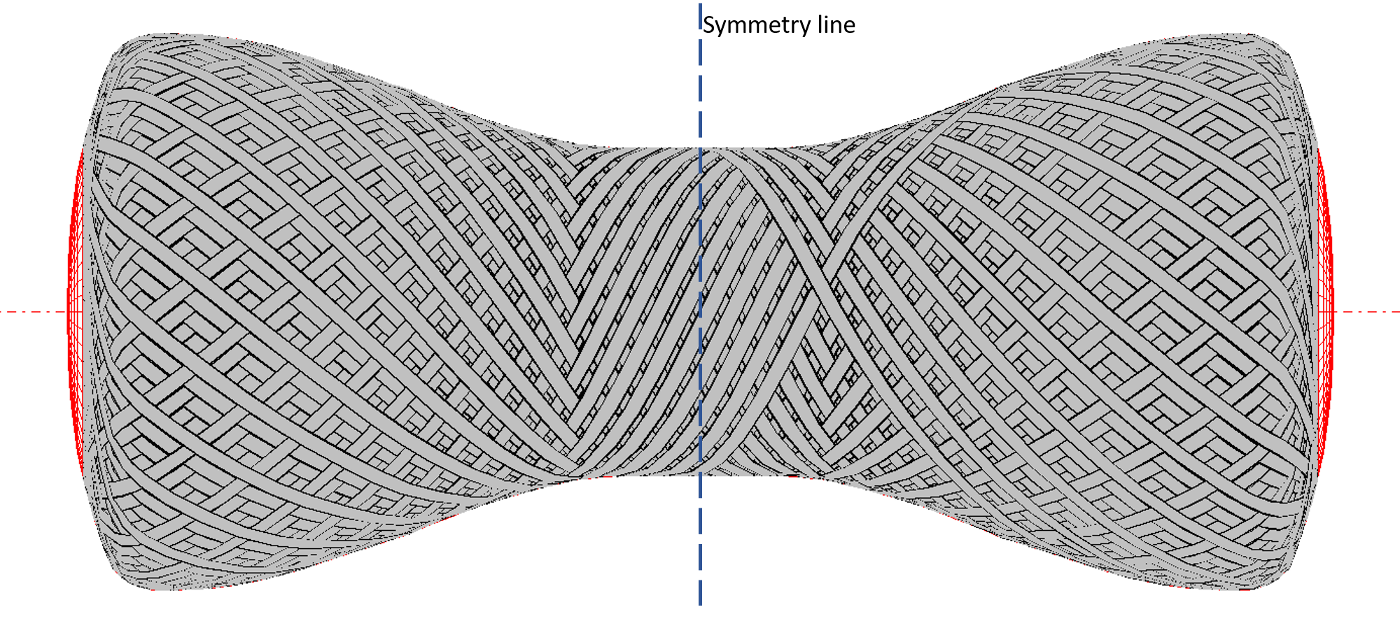
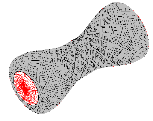
This example shows how to create a mandrel such as the one shown below, and how to create a fibre path for it. The process for this is also shown in the training video CTV010. There are a few key features about this mandrel to note:
The mandrel is a non-standard shape, this means that it cannot be wound using the parametric QuickCAD options. The mandrel is axisymmetric, which means that it can be wound in Cadfil Axsym, using XR data. Finally the mandrel has a plane of symmetry on the x axis, from the x- end to the x+ end. This plane of symmetry is shown as a dashed line on the drawing below.
This means that the symmetry options in Axsym can be used. This makes it simpler to generate the mandrel data in Axsym, and much easier to create the fibre paths on the mandrel. There are 2 ways a fibre path can be created, either by creating a path from a hoop point, or creating a path from the plane of symmetry.
Creating a symmetrical mandrel
Creating a fibre path from hoop point
Creating a fibre path from symmetry plane
Creating a symmetrical mandrel
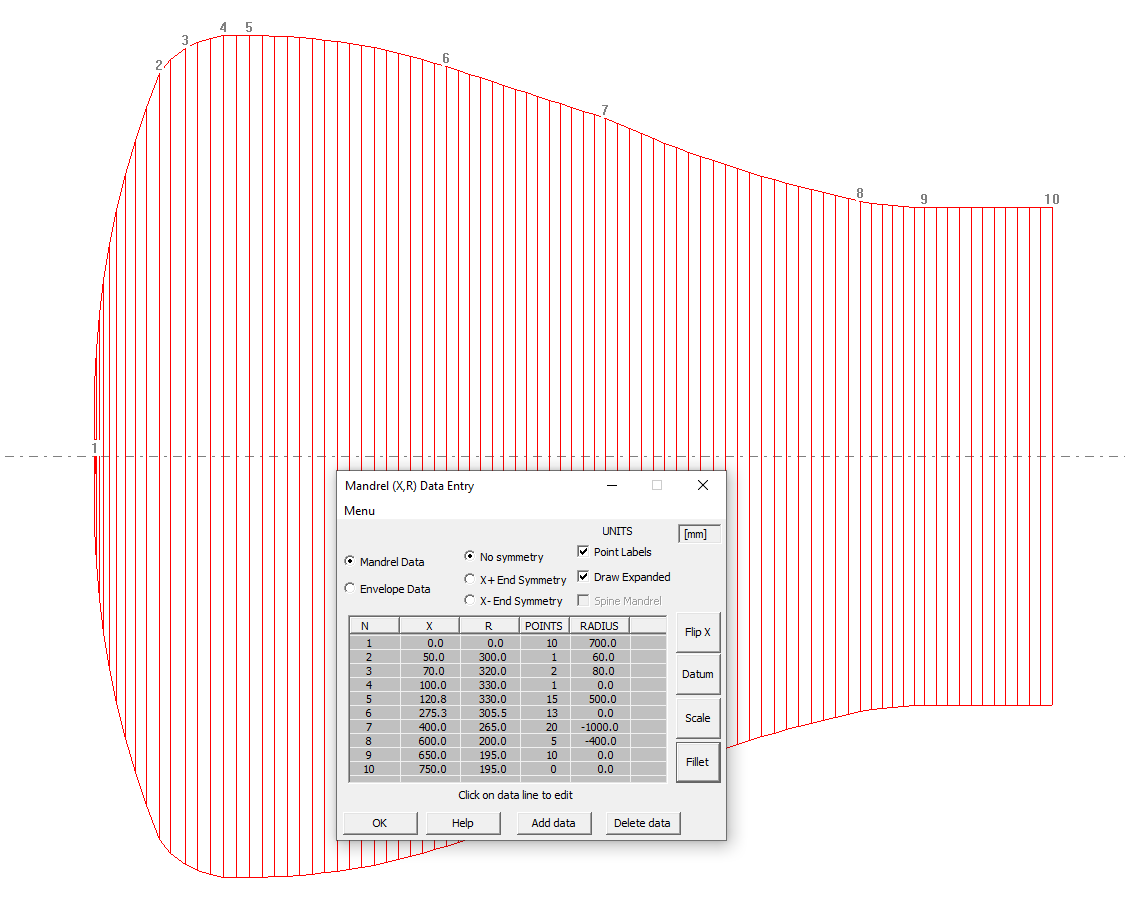
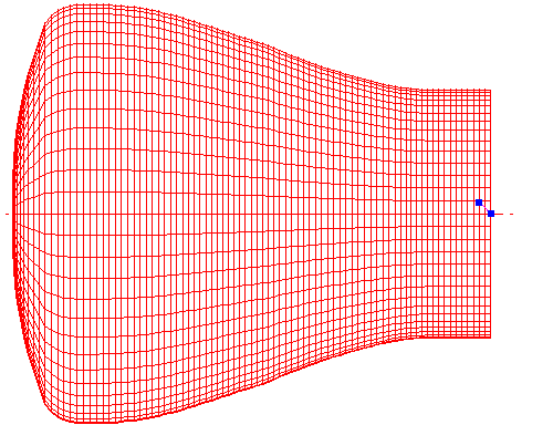
The first step is to create the mandrel in the Cadfil mandrel editor. This could be done through inputting XR data, or by importing CAD data from IGES or DXF. The mandrel will need to be created up to the plane of symmetry. It is possible to input the data for either the x- end or the x+ end of the mandrel. The diagram below shows the x- end. The x+ end will be created by symmetry.
At the point, the 'X+ End Symmetry' option can be used to generate the X+ side of the mandrel. Likewise if the X+ end has been specified in the mandrel editor, the 'X- End Symmetry' option will create the remaining half of the mandrel.
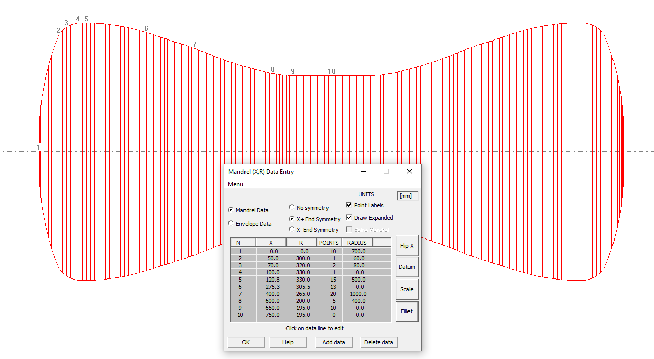
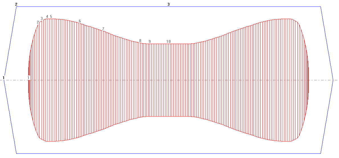
When the mandrel is complete, pressing 'ok' will create a default envelope, and at this point, the mandrel is complete. There are now 2 ways in which the fibre path can be created.
Creating a fibre path from hoop point
Once the mandrel is finished and saved, 'Fibre Path Create' can be selected from the main options menu to create the winding path. The newly created mandrel can be selected, and from here there are 2 ways to create the path. The first method that will be discussed is creating a path from a hoop point.
In this example the hoop point will be set at an x position of 20mm. This can be input by selecting the 'Enter X position' option, and selecting 'Hoop up' to create the hoop point. The path must go from the hoop point to the plane of symmetry.
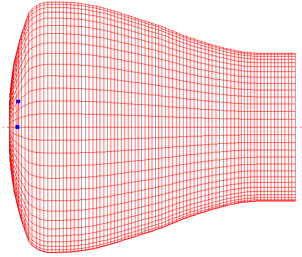
When this path is wound geodesically, it becomes clear that geodesic winding is not possible. The fibre turns and starts to travel in the reverse direction as shown below. Therefore some friction is required to reach the plane of symmetry.
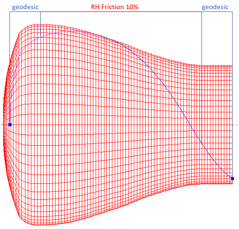
The solution shown below is a slightly more complex path. The first section to the widest part of the mandrel is geodesic. After this, the RH friction option is used at 10% to ensure that the fibre does not turn. Finally geodesic winding is used again as the path gets closer to the line of symmetry.
This is quite simple to do on half a mandrel with the symmetry option. If the symmetry option is not used, then the winding on the other half of the mandrel would be difficult. In order to make the winding look the same at both ends, the user would have to have opposite winding on the second half of the mandrel. Some geodesic winding, followed by a section of LH friction, and ending again with geodesic winding. The points at which the winding type would change would have to be exact, in order to make the winding symmetrical, and in order to make sure that the end opening radius was the same at both ends.
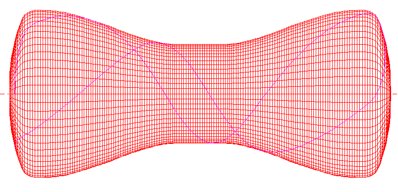
With the symmetric mandrel option shown above, Cadfil will automatically generate the path the other side of the plane of symmetry, so that it matches the path specified. Then, as is usual in Cadfil Axsym, Cadfil can automatically generate the return path, so that a complete circuit is formed.
When the path is finished, and saved, Cadfil will then ask to create a payout path. In this case, a band thickness of 20mm is used, and Cadfil calculates the number of circuits required, and gives the band pattern selection table shown below.
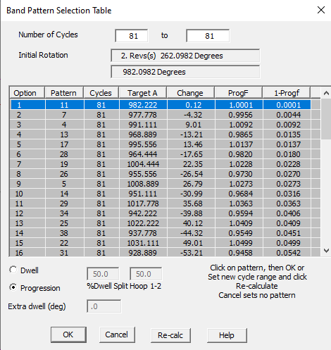
On selecting a band pattern, Cadfil will create the payout path. The full fibre path and band pattern pictures can be seen using the view options.
From here the payout path can be added to a combined programs file, or post-processed directly.
Creating a fibre path from symmetry plane
Previously, fibre path creation has been discussed where the path starts from the hoop point, and goes to the plane of symmetry. It is equally possible to create the fibre path in the reverse direction, from the plane of symmetry.
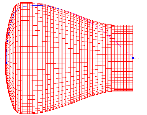
From the mandrel creation screen, it can be seen that the plane of reflection is at a x value of 750. Therefore this time, in the 'Fibre Path Create' the mandrel can be selected, followed by the 'Enter X position' option. A value of 750 is used, but this time, a wind angle is chosen instead of a hoop point.
When choosing the wind angle from the plane of rotation, a 45 degree angle is used in this example. However as it is in the reverse direction, an angle of 135 degrees is used (180-45). See fibre path start angle options for more details.
From this start point, the path is wound geodesically until it reaches the hoop point on the dome end. In this case, no friction was required. The hoop point is shown below.
Once the Fibre path is finished and saved, the payout path is created using the band pattern selection table, as discussed in the first method above.